Environmental monitoring system

a monitoring system and environmental technology, applied in the field of environmental monitoring systems, can solve the problems of complex installation, configuration and operation of multiple sensor systems, time-consuming, expensive and redundant,

Inactive Publication Date: 2005-05-03
PENTAGON TECH GROUP
View PDF43 Cites 159 Cited by
  • Summary
  • Abstract
  • Description
  • Claims
  • Application Information

AI Technical Summary

Benefits of technology

[0006]The present invention solves the aforementioned problems by providing an environmental monitoring system that automatically detects and performs all necessary setu

Problems solved by technology

Thus, installation, configuration and operation of multiple sensor

Method used


Image

  • Environmental monitoring system
  • Environmental monitoring system
  • Environmental monitoring system

Examples


Embodiment Construction

[0014]The present invention is an integrated, stand-alone clean room environmental monitoring system that integrates sensor configuration, operation and control using a single central unit that provides plug-and-play support for different types of sensors.

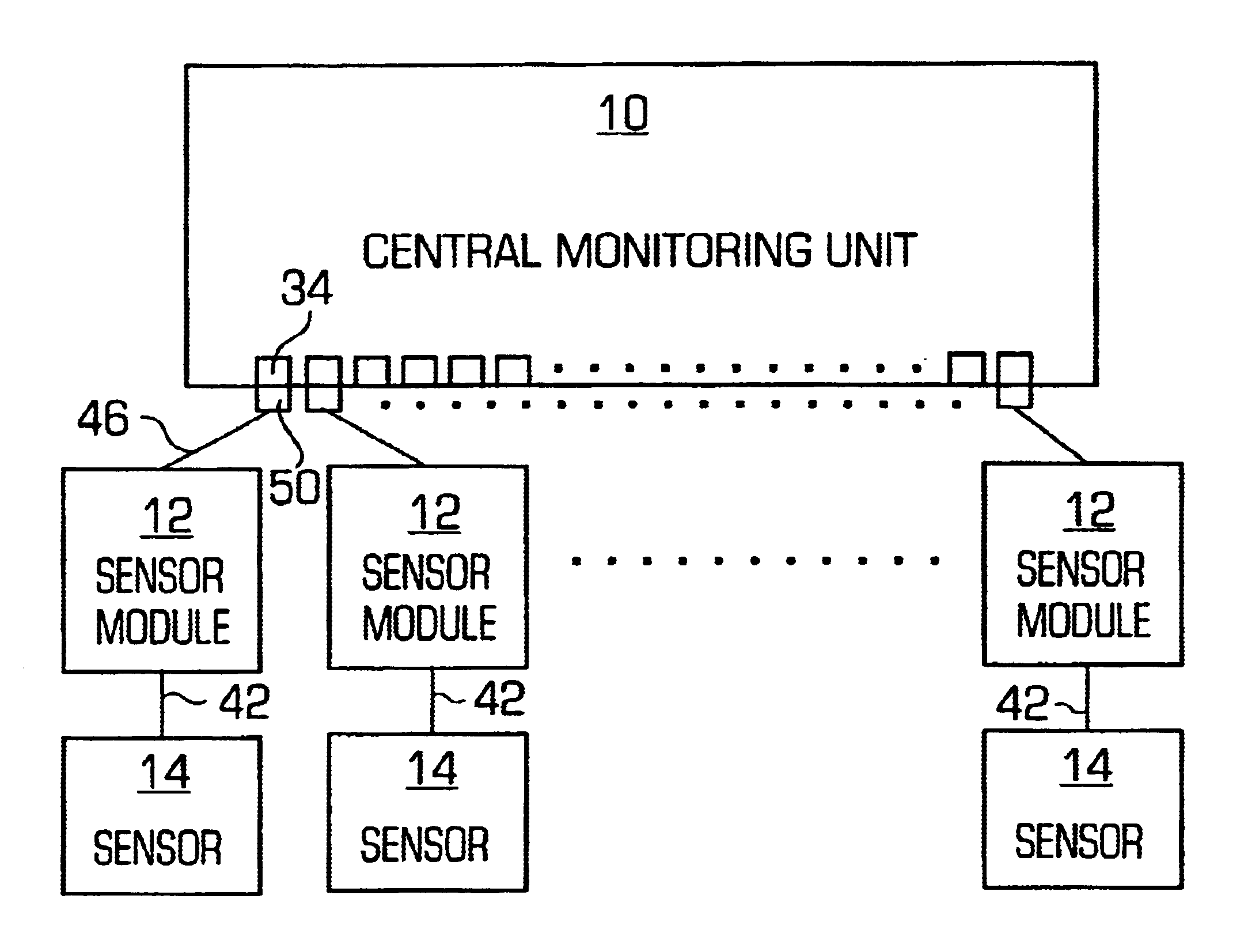
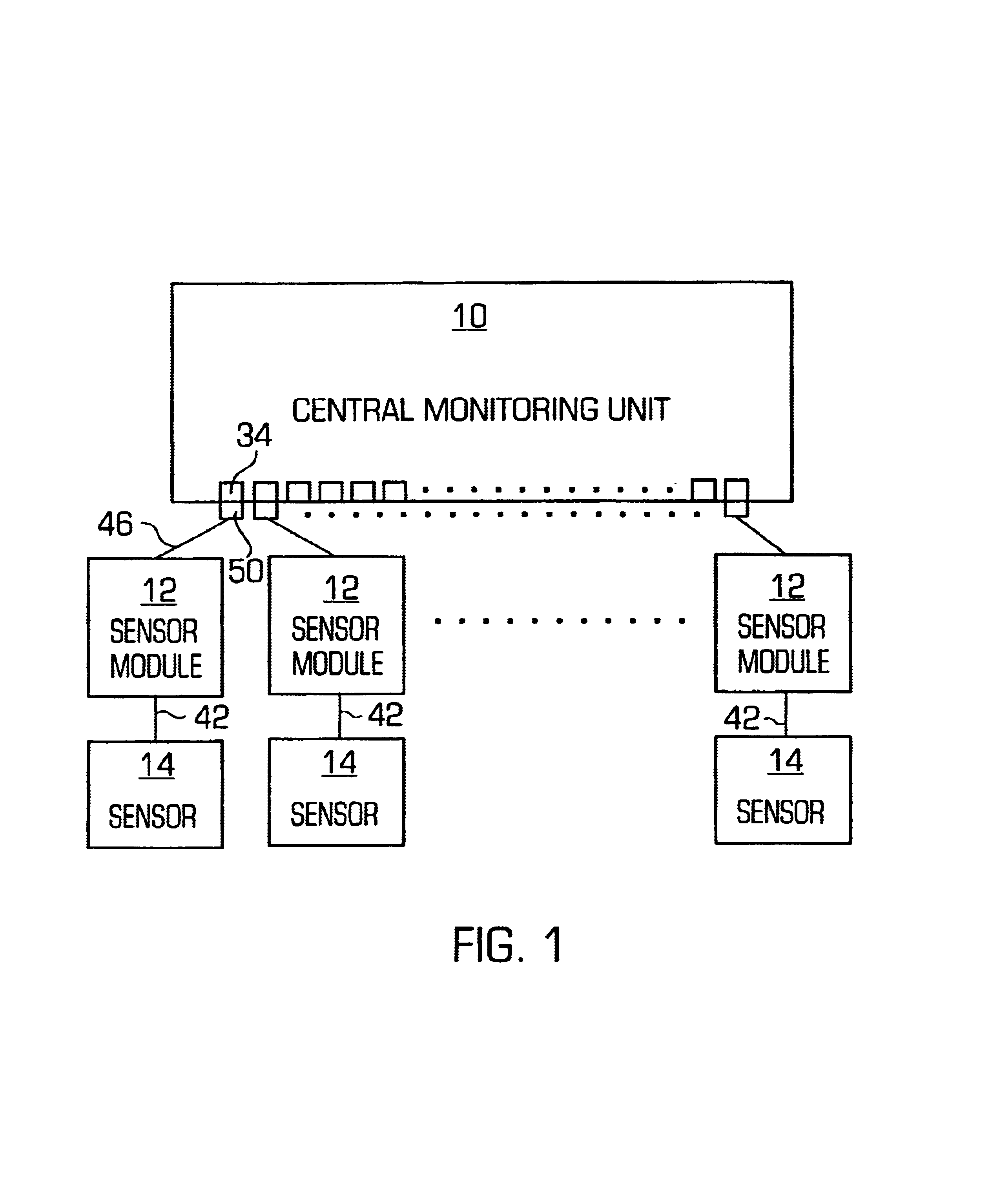
[0015]The monitoring system of the present invention is shown in FIG. 1, and includes a central monitoring unit 10, a plurality of sensor modules 12 and a plurality of sensors 14.

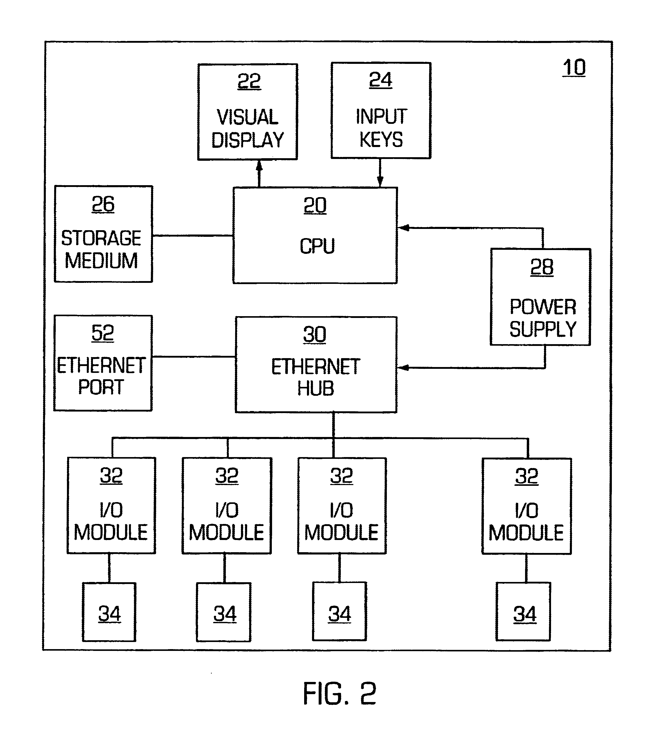
[0016]The central unit 10 is better shown in FIG. 2, and includes a central processing unit (CPU) 20 that is connected to a visual display 22, input keys 24, a storage medium 26, a power supply 28, and an Ethernet hub 30. Ethernet hub 30 is connected to a plurality of input / output (I / O) modules 32, which in turn are connected to a plurality of external electrical connectors 34. The power supply 28 provides one or more voltages (e.g. 5V, 12V, and / or 24V) not only to provide electrical power to operate the central unit components, but also to operate the sen...


PUM


Abstract

An environmental monitoring system is disclosed including a plurality of sensors, a plurality of sensor modules each electrically connected to one of the plurality of sensors for generating a ID signal that uniquely identifies the one sensor electrically connected thereto, a plurality of first electrical connectors each electrically connected to one of the sensor modules and a central monitoring unit that includes a plurality of second electrical connectors for connection with the first electrical connectors, a CPU for receiving the ID signals via the first and second electrical connectors for identifying each of the sensors in response to the received ID signals and for configuring operating parameters for each of the identified sensors, and a storage medium for storing sensor data corresponding to the sensor signals. Other elements of the monitoring system can include a power supply, at least one input/output module and calibration ports.

Description

[0001]This application claims the benefit of U.S. Provisional Application No. 60 / 300,590, filed Jun. 22, 2001, and entitled Environmental Monitoring System with Smart Sensors.FIELD OF THE INVENTION[0002]This invention relates generally to an environmental monitoring system (EMS) for clean room operation and contamination control, and more particularly to a system that automatically integrates a wide variety of environmental sensors of different types.BACKGROUND OF THE INVENTION[0003]It is well known to use sensors to monitor the environmental conditions in clean rooms that are used to make, for example, semiconductor devices. Numerous environmental conditions must be maintained, and therefore monitored, to ensure certain clean room specifications are met. Examples of such environmental conditions include temperature, relative humidity, air velocity, differential pressure between clean room areas, airborne particle counts, etc.[0004]Clean room environmental sensors serve several purp...

Claims


Application Information

Patent Timeline
IPC IPC(8): G01R31/26G06F11/00G08B29/00G06F19/00G08B23/00G06FG08C19/00
CPCG08C19/00
Inventor LUTZ, DONALD G.DUGGAN, DANIEL
Owner PENTAGON TECH GROUP
Why Eureka
Try Eureka