Pulse-radar method and pulse-radar sensor and system

a pulse-radar sensor and pulse-radar technology, applied in the field of pulse-radar methods, can solve the problems of substantial interference immunity within the system, high bandwidth of srr radar pulses, etc., and achieve the effect of reducing the mutual interference of radar sensors, reducing the interference of simultaneously active radar sensors, and simple time-slot switching

Inactive Publication Date: 2005-05-03
ROBERT BOSCH GMBH
View PDF14 Cites 44 Cited by
  • Summary
  • Abstract
  • Description
  • Claims
  • Application Information

AI Technical Summary

Benefits of technology

[0004]These measures make the pulse-radar method (SRR) effectively usable in short-range sensing in the first place, in particular for PPS and DAD. Without applying the measures according to the present invention, mutual interference would occur continually once a certain equipment level of motor vehicles had been reached.
[0021]Other refinements may effectively reduce mutual interference of radar sensors. In particular, the simultaneous use of different time slots for different radar sensors and the use of different polarizations results in substantial interference immunity within a system.

Problems solved by technology

The cause of this interference is the high bandwidth of the SRR radar pulses.
In particular, the simultaneous use of different time slots for different radar sensors and the use of different polarizations results in substantial interference immunity within a system.

Method used


Image

  • Pulse-radar method and pulse-radar sensor and system
  • Pulse-radar method and pulse-radar sensor and system
  • Pulse-radar method and pulse-radar sensor and system

Examples


Embodiment Construction

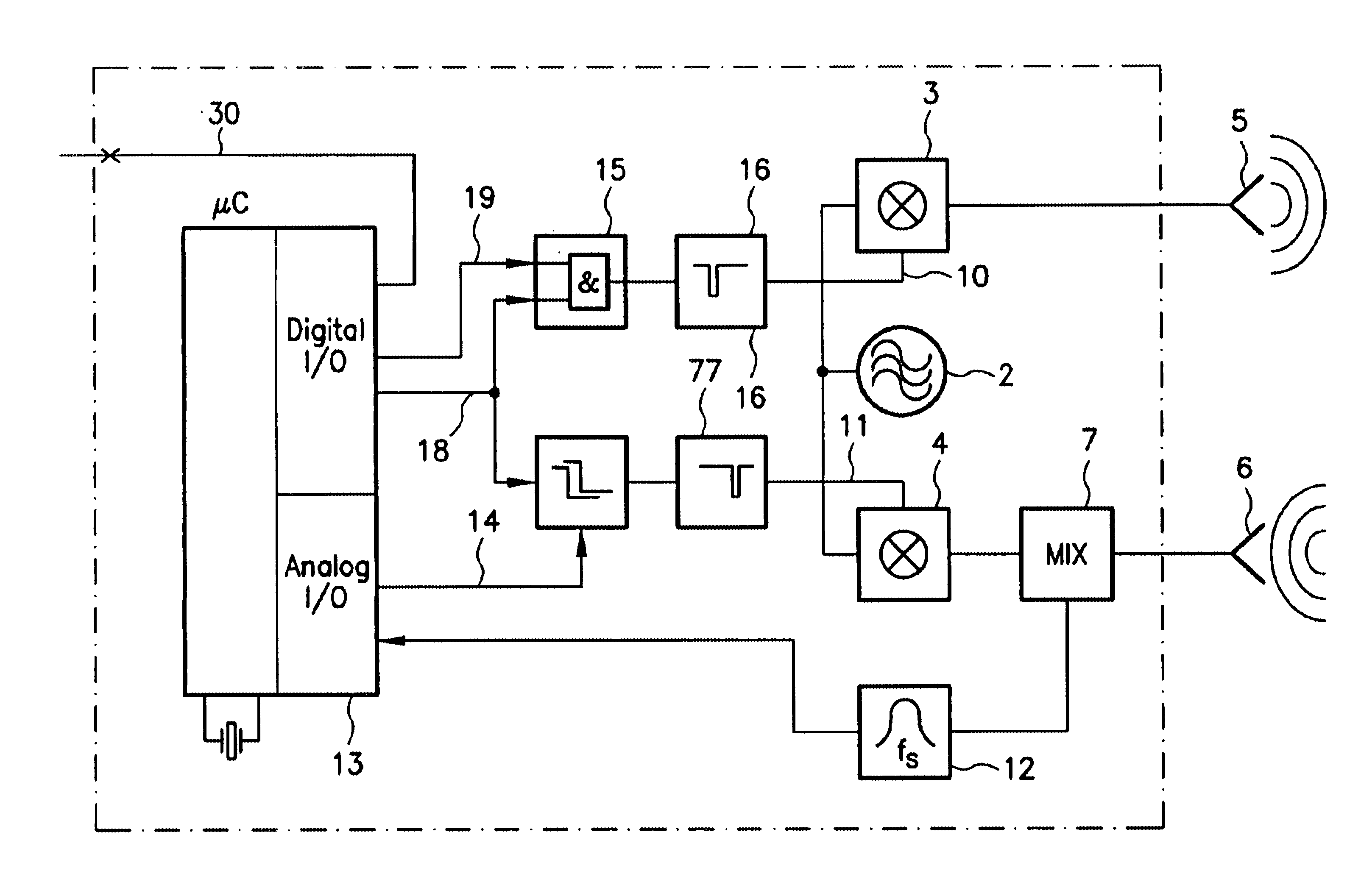
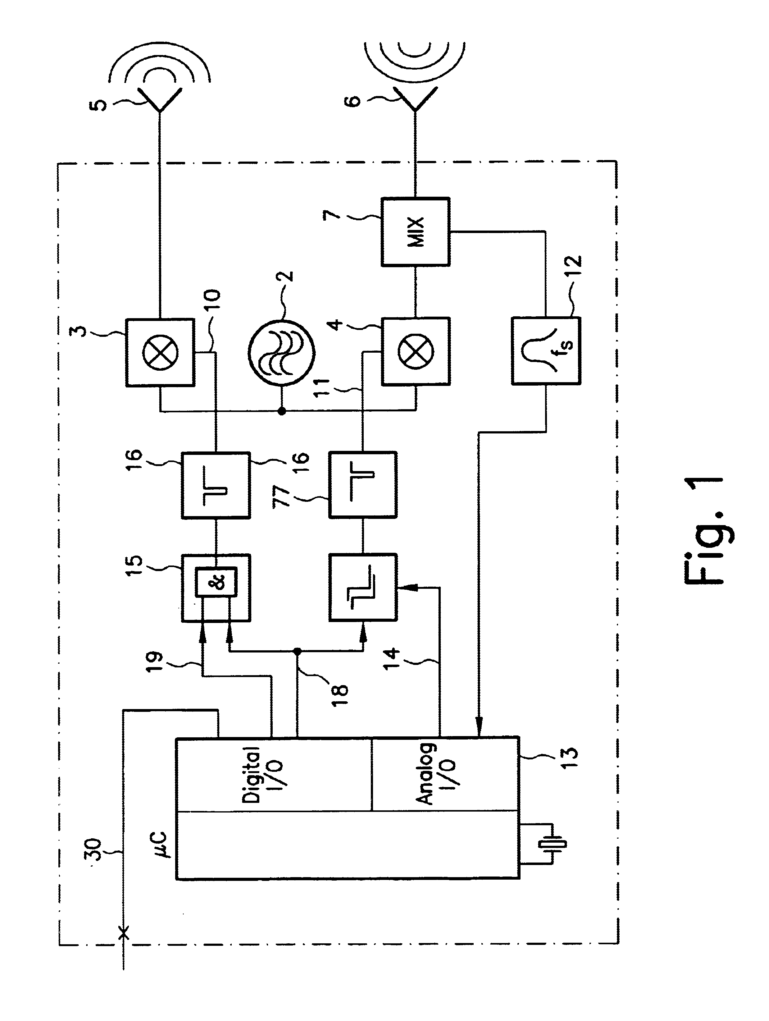
[0026]As shown in FIG. 1, a microwave-carrier oscillator 2 in radar sensor 1 generates a carrier frequency. With the aid of trigger-pulse-controlled fast switches 3 and 4, in particular diode switches, oscillation packets are formed from the continuous signal of carrier oscillator 2. Via an antenna 5, the oscillation packet formed via switch 3 is emitted. After reflection at a possible obstacle, parts of this signal are picked up by receiving antenna 6 and conveyed to a mixer 7. This mixer 7 mixes the oscillation packet formed via switch 4 with the incoming signal. Mixer 7 provides an output signal 8 if the received and the sampling signal (via switch 4) coincide in time. With the aid of a controllable pulse delay 9, the sampling pulse is delayed with respect to the transmission pulse, due to the fact that trigger pulse 11 for switch 4 is conveyed via pulse delay 9, whereas trigger pulse 10 reaches switch 3 without a delay. The control of pulse delay 9 is implemented by a control vo...


PUM


Abstract

In a pulse-radar method, in particular for motor vehicles, different time slots of a time frame are predefined. During one time slot, a radar sensor emits at least one radar pulse and receives the echo signal(s). During the remaining time slots the radar sensor monitors whether interference signals occur. On the basis of the interference signals occurring per time slot, a decision is made whether the radar sensor should continue its transmitting and receiving operation in the predefined time slot or should switch to one of the remaining time slots of the time frame. The method is suited for the concurrent operation of a plurality of radar sensors, without this causing interference.

Description

FIELD OF THE INVENTION[0001]The present invention is directed to a pulse-radar method, in particular for motor vehicles, in which occurring interference signals are monitored.BACKGROUND INFORMATION[0002]German Patent Application No. DE 196 31 590 describes a radar system that works according to a pulse-radar method. In the FMCW-radar method described, individual time periods are defined in which the oscillator emits modulated high-frequency signals. During at least one time period, no signals used for measuring radar targets are emitted. The interference signals occurring there are recorded and evaluated, together with recorded radar signals, so as to be able to classify them as possible wrong targets.SUMMARY[0003]In accordance with example embodiments of the present invention, it may be possible to avoid, or at least reduce, mutual interference of pulse-radar systems (short-range radar SRR), in particular when their detection ranges overlap and / or are directed toward each other. Th...

Claims


Application Information

Patent Timeline
Patent Type & Authority Patents(United States)
IPC IPC(8): G01S13/00G01S13/22G01S7/40G01S13/02G01S13/93G01S13/86G01S13/931
CPCG01S7/023G01S7/40G01S13/22G01S13/0209G01S2013/9389G01S13/86G01S13/931G01S2013/93275G01S7/0231G01S7/0235
Inventor RICHTER, KARL-HEINZ
Owner ROBERT BOSCH GMBH
Why Eureka
Try Eureka