Position sensor

a technology of position sensor and sensor output, which is applied in the direction of converting sensor output, transmission system, instruments, etc., can solve the problems of too expensive for embedding into hand-held portable communication and information devices, system response time decline, and system response time trade-o

Inactive Publication Date: 2005-05-03
SINNAPTIX
View PDF131 Cites 242 Cited by
  • Summary
  • Abstract
  • Description
  • Claims
  • Application Information

AI Technical Summary

Problems solved by technology

One problem with this system is that there is a trade-off between the system's response time and the accuracy of the tablet.
In particular, for high accuracy, a large number of overlapping loop coils are required, however, as the number of loop coils increases, the system's response time decreases.
Another problem with this system is that it has a relatively large “dead band” at the edge of the overlapping loop coils which causes problems when space is critical such as in hand-held computer devices such as PDAs and mobile telephones.
Another problem with this system is that it is too expensive for embedding into hand-held portable communication and information devices targeted at consumer markets.
However, the problem with using such resistive touch screens is that it degrades the LCD's contrast, it increases glare and reflections from other light sources, it suffers from wear and adds significantly to product thickness.
Further, it cannot cope with unintended contact with the touch screen because it does not differentiate between contact from different objects.
As a result, the user cannot rest their hand on the device when using it, which may prevent them from using their normal comfortable writing style.
One problem with the system described in the Applicant's earlier Interna

Method used


Image

  • Position sensor
  • Position sensor
  • Position sensor

Examples


Embodiment Construction

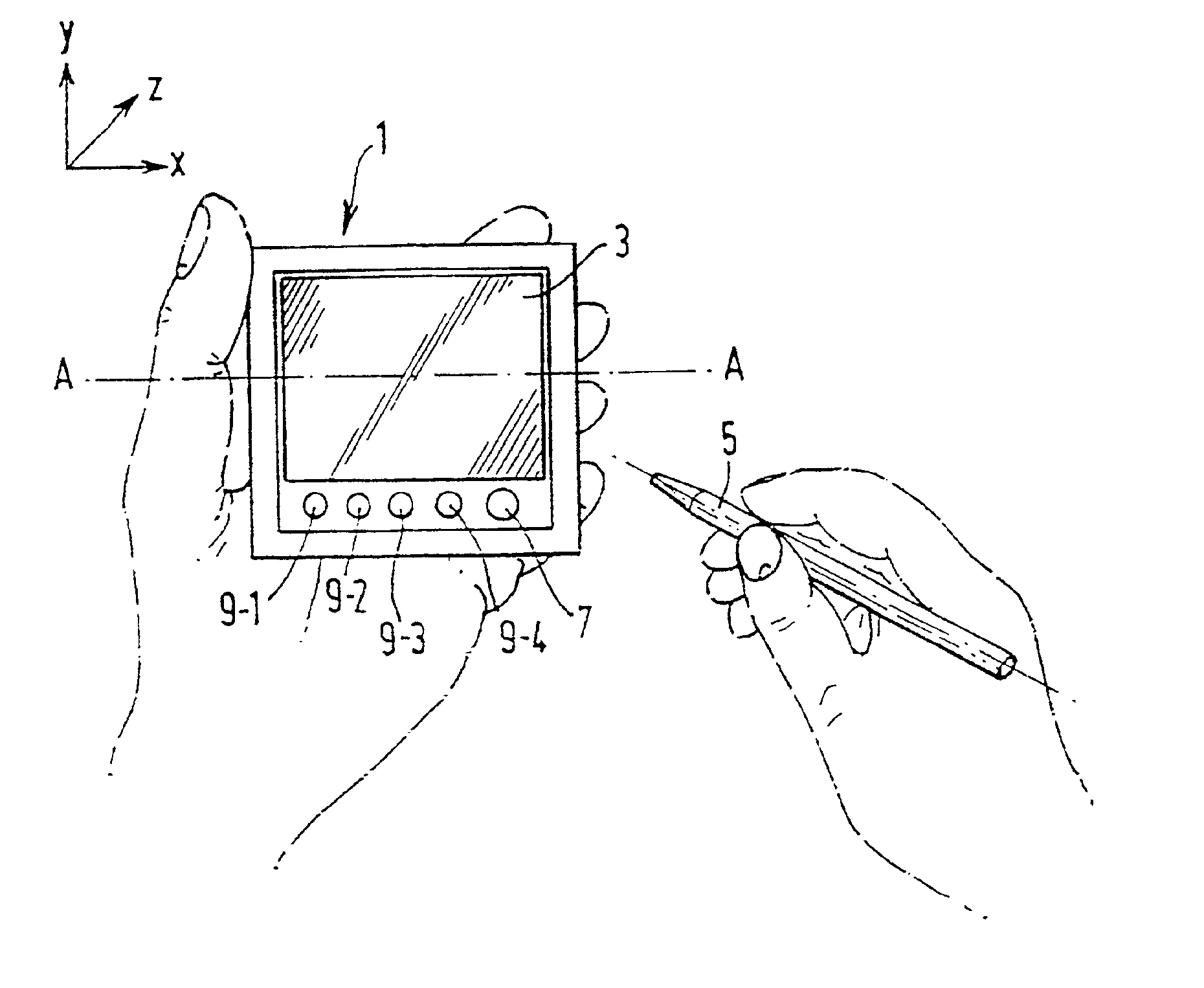
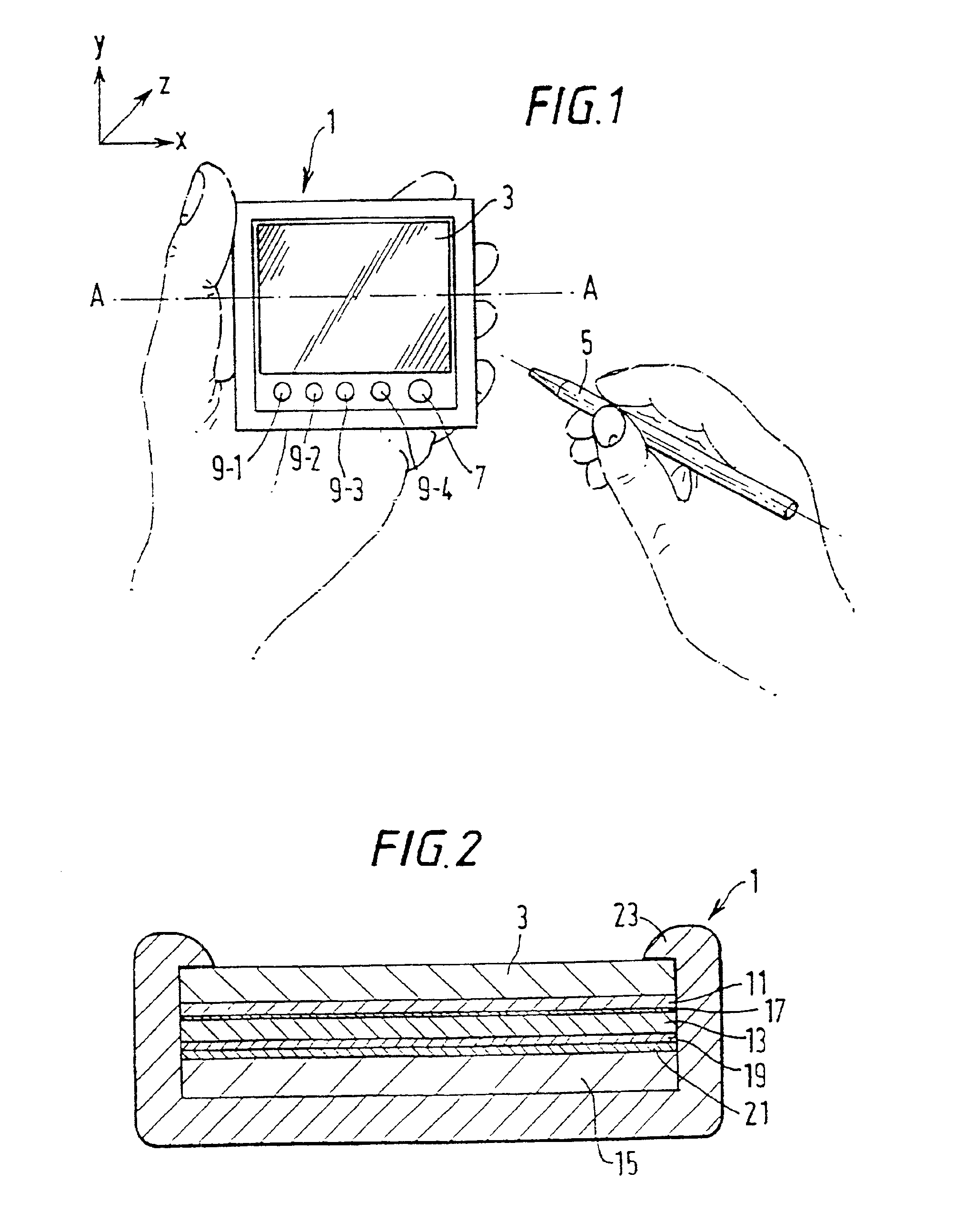
[0049]FIG. 1 shows a hand-held personal digital assistant (PDA) 1 which employs an x-y digitising system (not shown) which is located beneath a liquid crystal display 3 of the PDA 1. The x-y digitising system is operable to detect the presence and x-y position of a resonant stylus 5 relative to the LCD 3. The position signals output from the digitising system are used by the PDA 1 to control information that is displayed on the LCD 3 and to control the operating function of the PDA 1. As shown, the PDA 1 also includes a number of push buttons beneath the LCD 3 including an on-off button 7 and a number of control buttons 9-1 to 9-4 which are used to control different functions of the PDA 1.

[0050]FIG. 2 shows a cross-sectional view on A—A of the PDA 1 shown in FIG. 1. As shown, the PDA 1 includes a liquid crystal display 3 which, in this embodiment, is between 1.5 mm and 3 mm thick. Beneath the LCD 3, there is an electroluminescent backlight 11 for providing a backlight for the LCD 3....


PUM


Abstract

A low cost x-y digitising system is provided for use in consumer electronic devices, such as portable digital assistants, mobile telephones, web browsers and the like. The digitiser includes a resonant stylus, an excitation winding for energising the resonant stylus and a set of sensor windings for sensing the signal generated by the stylus, from which the x-y position of the stylus is determined.

Description

[0001]This is a divisional and / or continuation-in-part of prior commonly assigned U.S. application Ser. No. 09 / 754,218 filed Jan. 5, 2001 now U.S. Pat. No. 6,667,740 (naming Ely, Collins, Cauwood and Brace as inventors) and Ser. 09 / 627,423 filed Jul. 27, 2000 now U.S. Pat. No. 6,489,899 (naming Ely, Jones, England, McKinnon, Pettigrew, Dames and Howe as inventors).BACKGROUND OF THE INVENTION[0002]The present invention relates to a position sensor and to parts therefor. The invention has particular although not exclusive relevance to x-y digitising tablets which operate with a cordless stylus. The invention is particularly useful for embedding behind the display of a hand-held electronic device such as a personal digital assistant (PDA), mobile telephone, web browser or products embodying combinations of these.[0003]U.S. Pat. No. 4,878,553 discloses an x-y digitising tablet which uses a resonant stylus. The digitising tablet comprises a large number of overlapping but separate loop c...

Claims


Application Information

Patent Timeline
IPC IPC(8): G01D5/12G01D5/20G06F1/16G06F3/033G06F3/046G06F3/0354G06F3/041
CPCG01D5/2073G01D5/208G06F1/1626G06F3/046G06F3/03545G06F3/041G06F1/1643
Inventor ELY, DAVID T. E.DAMES, ANDREW N.
Owner SINNAPTIX
Why Eureka
Try Eureka