Fiber optic sensor for precision 3-D position measurement

a fiber optic sensor and position measurement technology, applied in the field of optical fiber-based sensors, to achieve the effect of accurate measurement of local curvature and torsion

Inactive Publication Date: 2005-05-03
DYNAMICS TECH
View PDF2 Cites 367 Cited by
  • Summary
  • Abstract
  • Description
  • Claims
  • Application Information

AI Technical Summary

Benefits of technology

[0013]The central system component of the present invention is a flexible “smart cable” which enables accurate measurement of local curvature and torsion along its length. These quantities are then used to infer the position and attitude of one end of the cable relative to the other. The technology does not require a coherent source or time domain measurements, thus eliminating some technical difficulties associated with standard approaches to distributed optical fiber measurements.

Problems solved by technology

However, only two or three frequencies were envisioned because their application was to locate a single hot spot of limited spatial extent.

Method used


Image

  • Fiber optic sensor for precision 3-D position measurement
  • Fiber optic sensor for precision 3-D position measurement
  • Fiber optic sensor for precision 3-D position measurement

Examples


Embodiment Construction

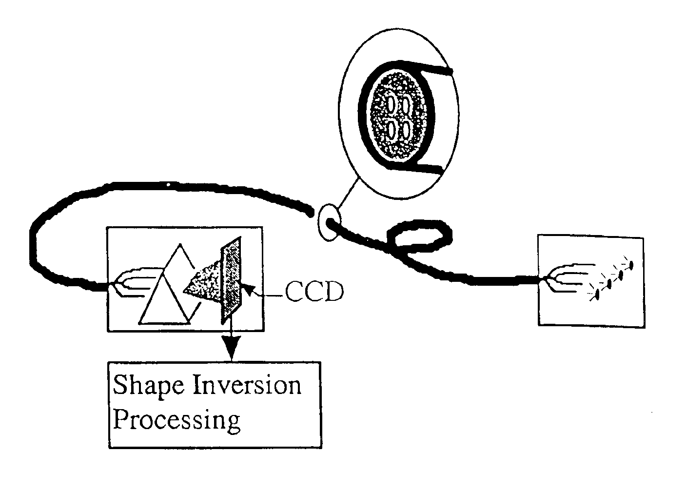
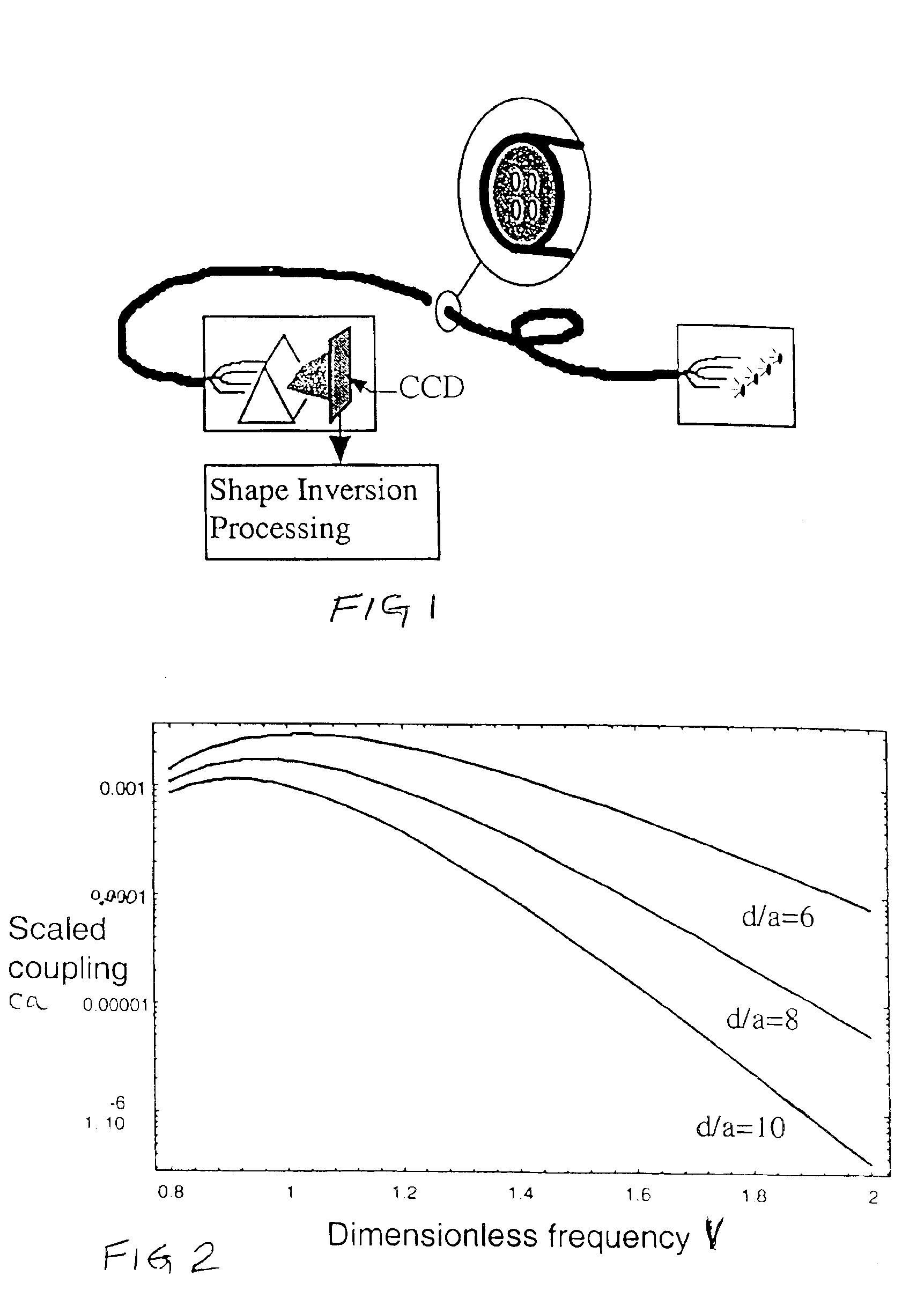
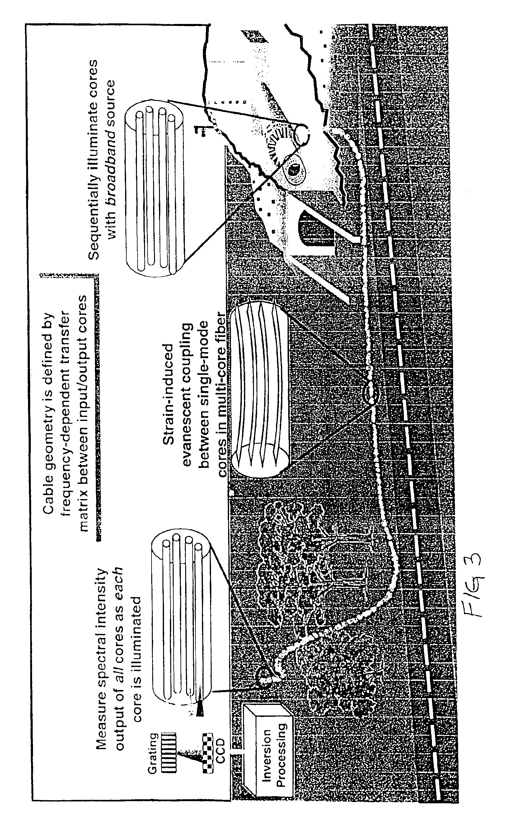
[0019]FIG. 1 is a sketch of the preferred embodiment of the invention. At one end of the fiber, the cores are illuminated sequentially by a broadband source and at the other end, the output intensities are resolved spectrally with a grating or prism and sensed with a CCD. The system is described by a frequency-dependent transfer matrix relating input to output core intensities. In general this transfer matrix is a strongly nonlinear function of the cable shape. A shape inversion algorithm which can cope with this nonlinearity is used to define the precise shape of the fiber cable.

[0020]In general terms, the invention may have various embodiments which take into account the following:[0021]1. The relation between local fiber curvature and torsion and intercore mode coupling (cross-talk).[0022]2. The shape inversion algorithm which functions over a useful range of cable configurations.[0023]3. The minimum number of fiber cores required in principle to reconstruct cable shape from inte...


PUM

PropertyMeasurementUnit
spectral intensitiesaaaaaaaaaa
flexibleaaaaaaaaaa
spectral intensity measurementaaaaaaaaaa

Abstract

The central system component of the present invention is a flexible “smart cable” which enables accurate measurement of local curvature and torsion along its length. These quantities are then used to infer the position and attitude of one end of the cable relative to the other. Sufficiently accurate measurements of the local curvature and torsion along the cable allow reconstruction of the entire cable shape, including the relative position and orientation of the end points. The smart cable for making these measurements comprises a multicore optical fiber, with individual fiber cores constructed to operate in the single mode regime, but positioned close enough to cause cross-talk (mode coupling) between cores over the length of the fiber. This cross-talk is very sensitive to the distribution of strains (curvature and torsion) along the cable.

Description

BACKGROUND OF THE INVENTION[0001]1. Field of the Invention[0002]The present invention relates generally to optical fiber-based sensors and more particularly to a fiber optic sensor for precision 3-D position measurement using mode coupling between single-mode fiber cores in a multi-core optical fiber.[0003]2. Background Art[0004]The idea of using multicore optical fibers for sensors has been known since the late 70's, when much of the seminal work on optical waveguide coupling was published. Meltz and Snitzer were granted patents (Meltz and Snitzer, 1981; Snitzer and Meltz, 1981) in 1981 for a fiber optic strain sensor and for a fiber optic hot spot detector which rely on the cross-talk phenomenon in multicore fibers. Their hot spot detector also features the innovation of multifrequency interrogation for localization along the fiber. However, only two or three frequencies were envisioned because their application was to locate a single hot spot of limited spatial extent. The major ...

Claims


Application Information

Patent Timeline
Patent Type & Authority Patents(United States)
IPC IPC(8): G01D5/353G01D5/26G01B11/03G01L1/24
CPCG01L1/242G01D5/3538G01D5/35341
Inventor CLEMENTS, GREGORY MINOT
Owner DYNAMICS TECH
Why Eureka
Try Eureka