AI technical title is built by PatSnap AI team. It summarizes the technical point description of the patent document.
a current sensor and relay technology, applied in circuit-breaking switches, instruments, printers, etc., can solve the problems of affecting the entire system, unsuitable addition to existing power systems to detect fault conditions within power cables, and costly installation of sensors and controls, so as to reduce the time required to install both the switch circuit and the sensor circuit, reduce the number of backup parts and troubleshooting time, and reduce the effect of time-consuming
Inactive Publication Date: 2005-05-03
VERIS INDS
View PDF13 Cites 30 Cited by
Summary
Abstract
Description
Claims
Application Information
AI Technical Summary
This helps you quickly interpret patents by identifying the three key elements:
Problems solved by technology
Method used
Benefits of technology
Benefits of technology
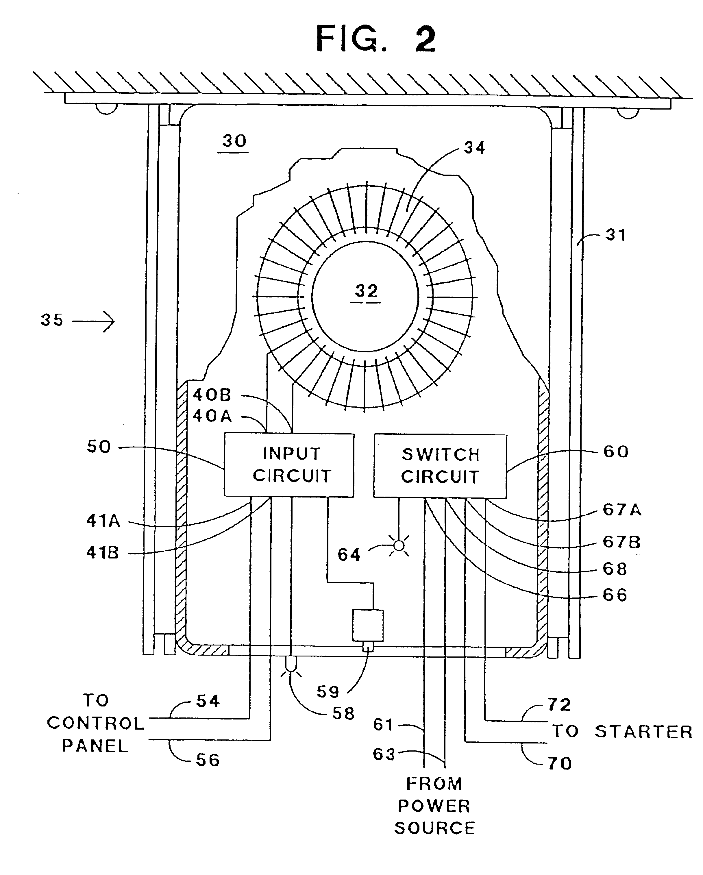
[0014]By locating the sensor circuit, which is a combination of the transformer and the input circuit, and the switch circuit proximate to one another within the single package, significant advantages are realized. Due to the limited available space within a starter housing, the single package is more desirable. The expense of manufacturing a single package is frequently less than manufacturing two separate packages. The time required to install both the switch circuit and the sensor circuit is reduced by only requiring installation of one combined package. A reduction in the number of backup parts and troubleshooting time is also realized.
[0015]In a preferred package a mounting bracket includes a slide arrangement to support the transformer so that its position can be adjusted easily to the best location with respect to the power cable.
Problems solved by technology
While this has long been possible, it has been costly to install the required sensors and controls.
Integrating the motor starter and protection circuit into one device makes it unsuitable for addition to existing power systems to detect fault conditions within power cables.
However, when a starter including such an integrated protection circuit is used in a system where the associated electrical device is interdependent with other electrical devices, use of such a starter to independently enable and disable the electrical device may result in devastating effects to the entire system.
However, many starter designs do not include an integrated protection circuit and also include no-fault detection.
The relay and current sensor in the past have been separate individual devices, each requiring a mounting location that may not be available within the starter housing due to limited space.
Additionally, it takes additional time to install two separate devices and requires stocking two separate replacement parts for use in the event of device failure.
Also, troubleshooting likely requires the inspection of both devices.
Method used
Image
Click on the blue label to locate the original text in one second.
Reading with bidirectional positioning of images and text.
Examples
Embodiment Construction
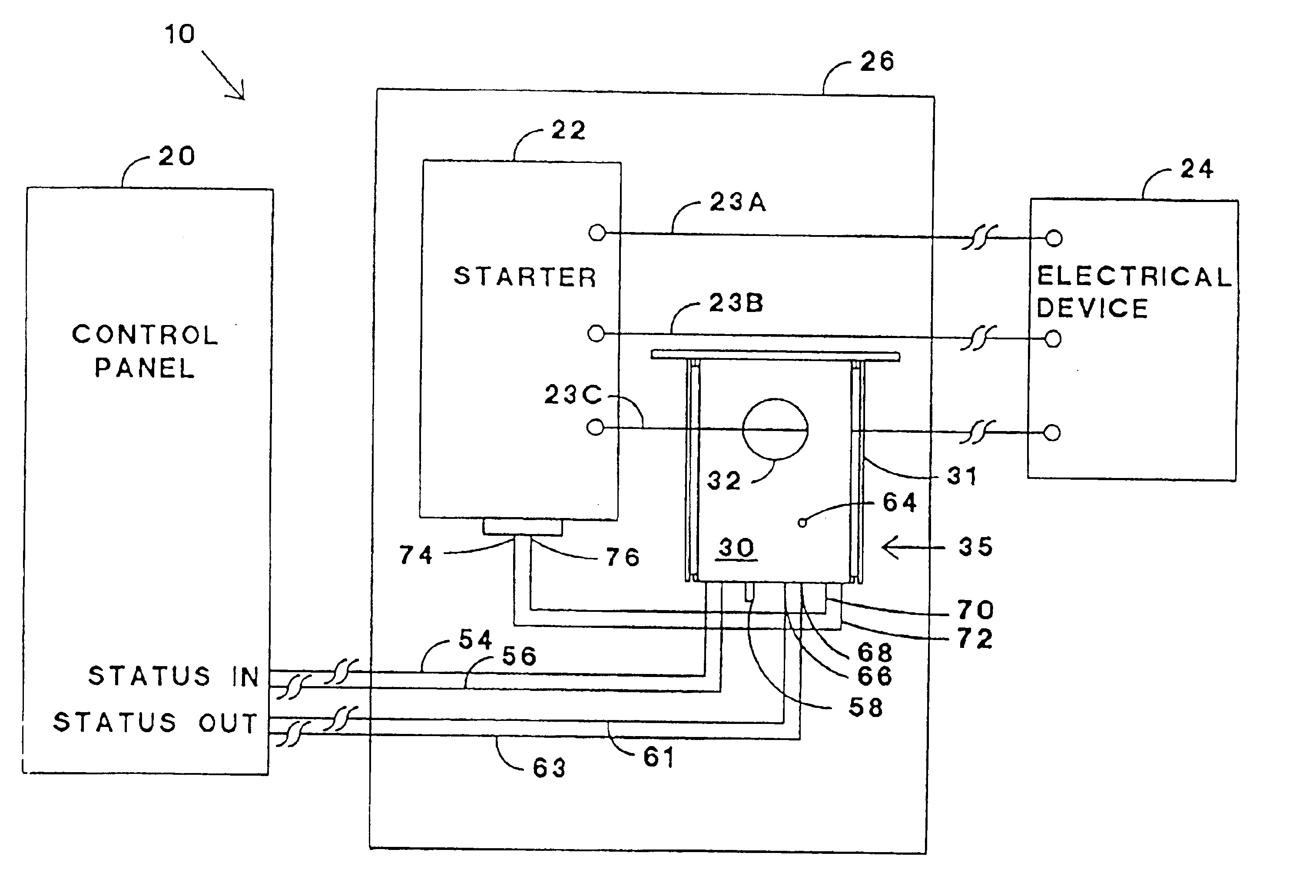
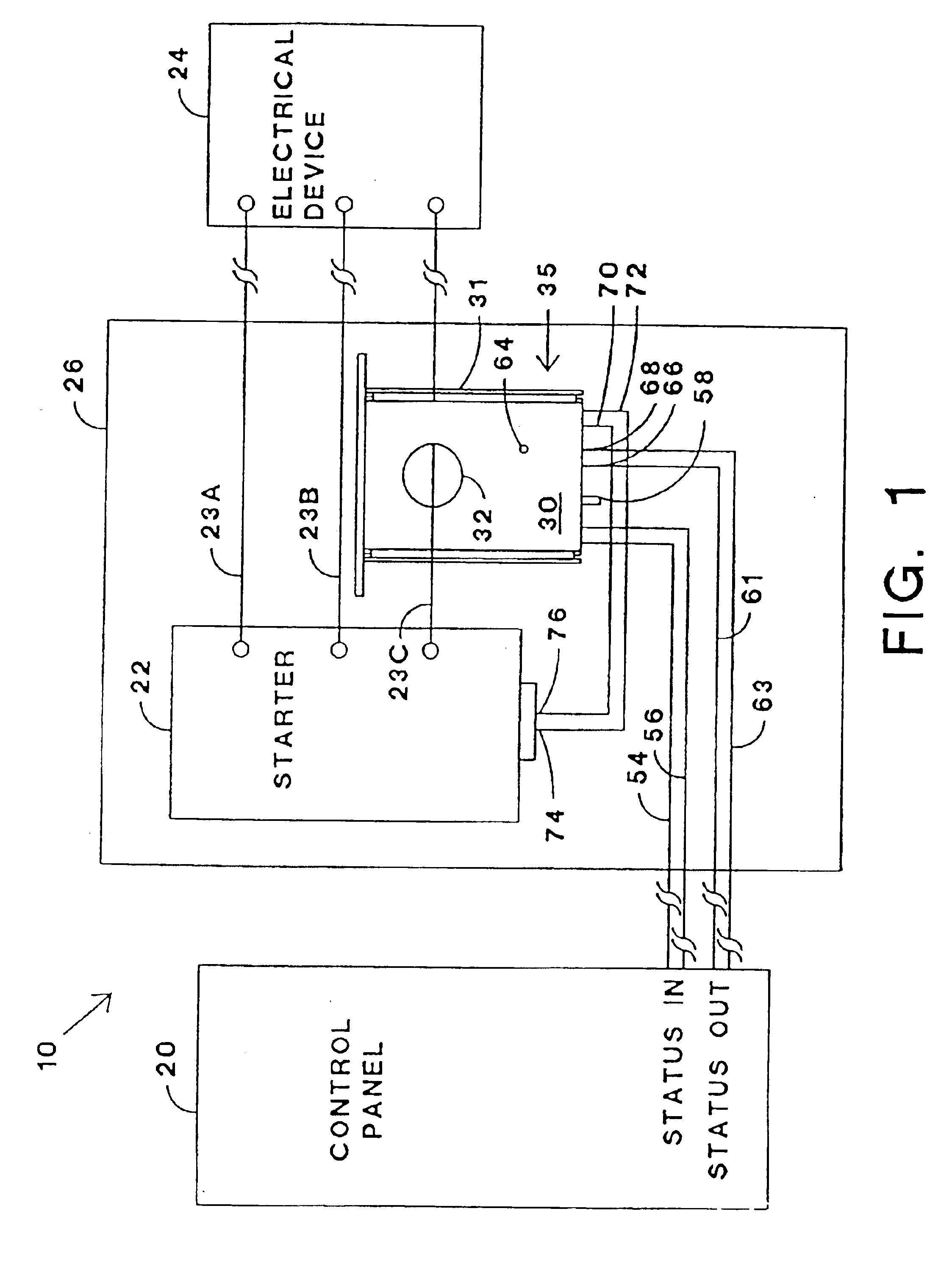
[0024]Referring to FIG. 1, an electrical system 10 includes a control panel 20 that utilizes a digital computer to provide effective control of many associated electrical devices. The centralized control panel 20 determines the effects on the entire system 10, or a portion of the system 10, of enabling or disabling an electrical device. For example, such associated electrical devices may include motors, pumps, fans, valves, generators, switches, lights, etc. One type of control panel 20 is generally known as a programmable logic controller, such as those sold by Allen Bradley.
[0025]A starter 22, designed to start (energize) and stop (de-energize) remotely located electrical devices, is electrically connected to an associated electrical device 24 by three power cables 23a, 23b, and 23c. Each starter 22 is usually located within an individual starter housing 26 which is a part of a substation. Most substations are not large, so it is desirable to reduce the size of the housing 26, so ...
PUM
Property
Measurement
Unit
voltage
aaaaa
aaaaa
thickness
aaaaa
aaaaa
thickness
aaaaa
aaaaa
Abstract
A protection device for monitoring current in a power cable to an electrical device and for controlling a remotely located starter for the electrical device in response to a system controller. The device includes a transformer magnetically linked with the power cable to produce a voltage signal in response to the presence of a changing current within the power cable. An input circuit located in a single housing together with the transformer is electrically connected to the transformer so as to receive the voltage signal. The input circuit produces, in response to the voltage signal, either a first signal or a first circuit condition at the output terminal of the input circuit, representative of the changing current in the power cable. A switch circuit also in the same container with the transformer has a terminal for sensing either a second signal or a second circuit condition of the remotely located system controller. The switch circuit has a second terminal to provide either a third signal or a third circuit condition effective to control the starter, in response to sensing one of the second signal and the second circuit condition. All of the transformer, the input circuit, and the switch circuit are located in a single unitary package which is easily mounted and adjusted to a desired position.
Description
[0001]This application is a continuation of Ser. No. 10 / 052,248, filed Jan. 18, 2002, now U.S. Pat. No. 6,724,600, which is a continuation of Ser. No. 09 / 784,084, filed Feb. 16, 2001, now U.S. Pat. No. 6,563,565, which is a continuation of Ser. No. 09 / 438,216, filed Nov. 12, 1999, now U.S. Pat. No. 6,219,216, which is a continuation of Ser. No. 09 / 264,367, filed Mar. 8, 1999 now abandoned, which is a continuation of Ser. No. 09 / 057,730, filed Apr. 8, 1998, now U.S. Pat. No. 6,005,760.[0002]This application claims priority of U.S. Pat. No. 6,724,600; which is a continuation of U.S. Pat. No. 6,377,430; which is a continuation of U.S. Pat. No. 6,219,216; which is a continuation of U.S. patent Ser. No. 09 / 264,67, filed Mar. 8, 1999; which is a continuation of U.S. Pat. No. 6,005,760; which is a continuation of U.S. Pat. No. 5,808,846.BACKGROUND OF THE INVENTION[0003]The present invention relates to a single protection device, including a transformer, an input circuit, and a switch circu...
Claims
Application Information
Patent Timeline
Application Date:The date an application was filed.
Publication Date:The date a patent or application was officially published.
First Publication Date:The earliest publication date of a patent with the same application number.
Issue Date:Publication date of the patent grant document.
PCT Entry Date:The Entry date of PCT National Phase.
Estimated Expiry Date:The statutory expiry date of a patent right according to the Patent Law, and it is the longest term of protection that the patent right can achieve without the termination of the patent right due to other reasons(Term extension factor has been taken into account ).
Invalid Date:Actual expiry date is based on effective date or publication date of legal transaction data of invalid patent.

