Sanitizing cabinet for sports equipment

Inactive Publication Date: 2005-05-10
SILVER STEVE
View PDF6 Cites 81 Cited by
  • Summary
  • Abstract
  • Description
  • Claims
  • Application Information

AI Technical Summary

Benefits of technology

[0010]It is an object of the present invention to provide a method and apparatus which would sanitize sports equ

Problems solved by technology

The tight sealing is required to prevent the escape

Method used


Image

  • Sanitizing cabinet for sports equipment
  • Sanitizing cabinet for sports equipment
  • Sanitizing cabinet for sports equipment

Examples


Embodiment Construction

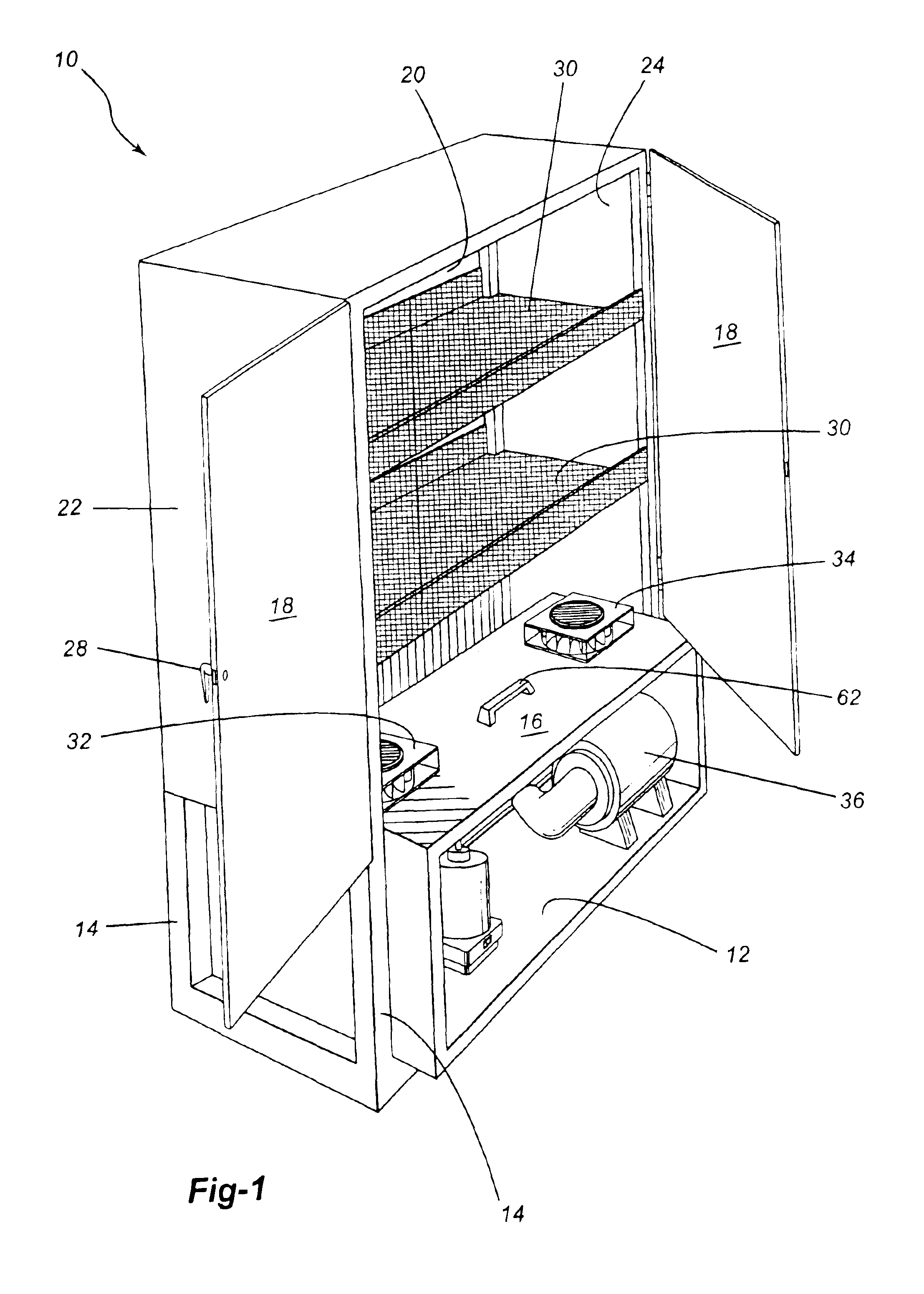
[0025]As shown in FIGS. 1 and 2, there is provided a sterilizing cabinet which is generally designated by reference numeral 10. Sterilizing cabinet 10 includes a base member 12 and four structural uprights 14 extending upwardly therefrom.

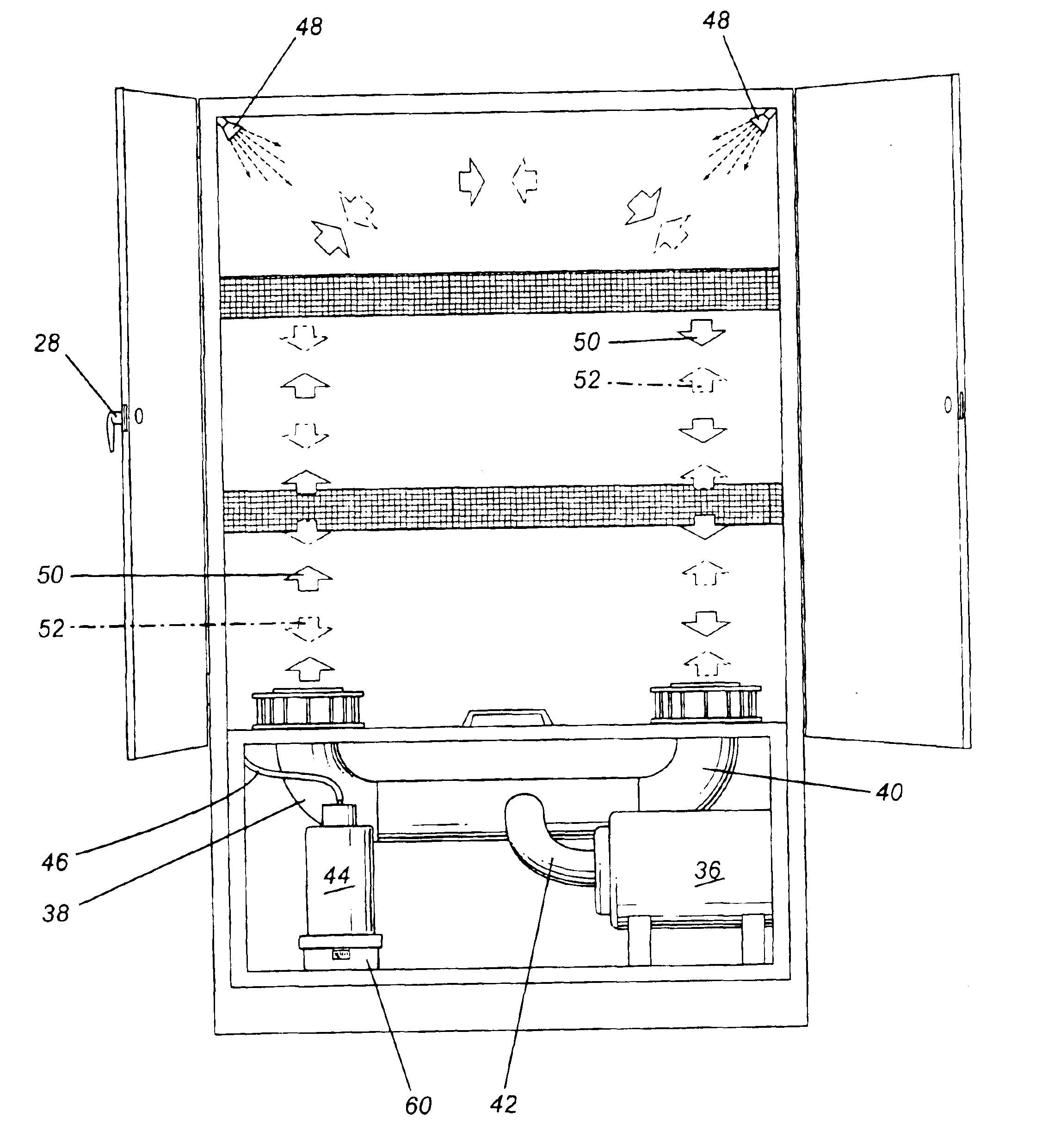
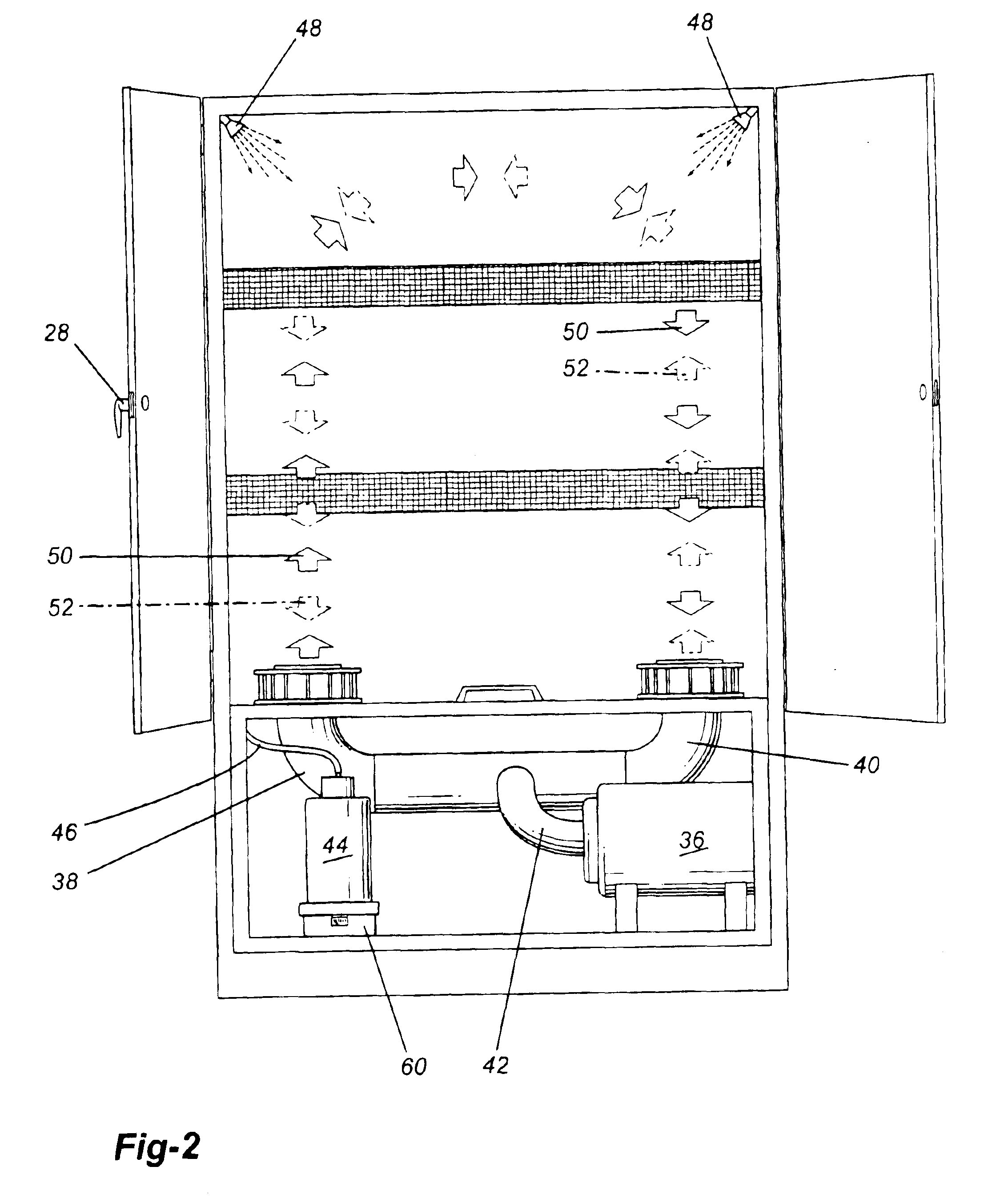
[0026]A compartment is defined by a compartment floor 16, a front panel 18, a rear panel 20, and a pair of side panels 22, 24. As will be seen in FIG. 1, a pair of front panels 18 are hingedly connected. When closed, a locking handle 28 is designed to engage the other front panel 18 to maintain the compartment tightly sealed.

[0027]Placed within sanitizing cabinet 10 above floor 16 are a pair of foraminous shelves 30. Foraminous shelves 30 may be of various types of structures, either a mesh or using wires.

[0028]Mounted in floor 16 is a first fan assembly 32 which is adjacent side wall 22 and a second fan assembly 34 which is adjacent side panel 24.

[0029]Mounted in the lower portion of sanitizing cabinet 10 below floor 16 is an ozone generator 36.

[00...


PUM


Abstract

There is provided a method and apparatus for sanitizing sports equipment which comprises a cabinet which can be sealed, first and second conduits in fluid communication with the cabinet, an ozone generator, and fans for circulating ozone containing gas through the conduits into the cabinet, the fans being operative to circulate the ozone containing gas in a first direction and subsequently in a reverse direction. There is also provided a fluid storage device, the fluid storage device being associated with a spray action to spray the fluid into the cabinet after the ozone has been circulated.

Description

[0001]The present application is a continuation-in-part of application Ser. No. 10 / 140,398 filed May 7, 2002, now abandoned.FIELD OF THE INVENTION[0002]The present invention relates to an apparatus and a method for treating sports gear to sanitize the same.BACKGROUND OF THE INVENTION[0003]The problem of odors, mold, and mildew associated with sports equipment is common. Thus, while clothing and apparel can be washed and dried in a normal manner, much equipment cannot be subject to these processes. For example, in the sport of hockey, skates and protective pads and other paraphernalia cannot be put in commercial washers and dryers. Similarly, shoes and pads from other sports such as soccer and basketball cannot be washed and dried in a conventional manner.[0004]It is known in the art, as shown in U.S. Pat. No. 5,369,893, that one may use self-contained dryers for accommodating sports equipment. The dryers have walls which cause heated air to recirculate in the drying chambers to decr...

Claims


Application Information

Patent Timeline
IPC IPC(8): F26B21/02F26B21/14F26B9/06
CPCF26B9/06F26B21/14F26B21/022
Inventor SILVER, STEVE
Owner SILVER STEVE
Why Eureka
Try Eureka