Coolant recovery system

a cooling system and cooling vapor technology, applied in the field of electronic cooling systems, can solve the problems of increasing the overall cost of spray cooling thermal management, not being suitable for reducing coolant loss, and significant loss of coolant vapor, so as to reduce the cost of operating a thermal management system, reduce the cost of cooling loss, and reduce the effect of cooling loss

Inactive Publication Date: 2005-05-10
PARKER INTANGIBLES LLC
View PDF28 Cites 41 Cited by
  • Summary
  • Abstract
  • Description
  • Claims
  • Application Information

AI Technical Summary

Benefits of technology

[0019]A second object is to provide a coolant recovery system that reduces coolant loss within thermal management systems.
[0020]Another object is to provide a coolant recovery system that reduces the costs of operating a thermal management system utilizing coolant.
[0021]An additional object is to provide a coolant recovery system that is energy efficient and flexible.

Problems solved by technology

However, costly dielectric coolant is lost through vapor loss that increases the overall cost of spray cooling thermal management.
In any application of spray cooling thermal management, coolant vapor loss is a significant issue.
While conventional thermal management systems may be suitable for the particular purpose to which they address, they are not as suitable for reducing coolant loss.
Conventional spray cooling thermal management systems may have significant coolant vapor loss, which would increase the thermal management costs.

Method used


Image

  • Coolant recovery system
  • Coolant recovery system
  • Coolant recovery system

Examples


Embodiment Construction

A. Overview

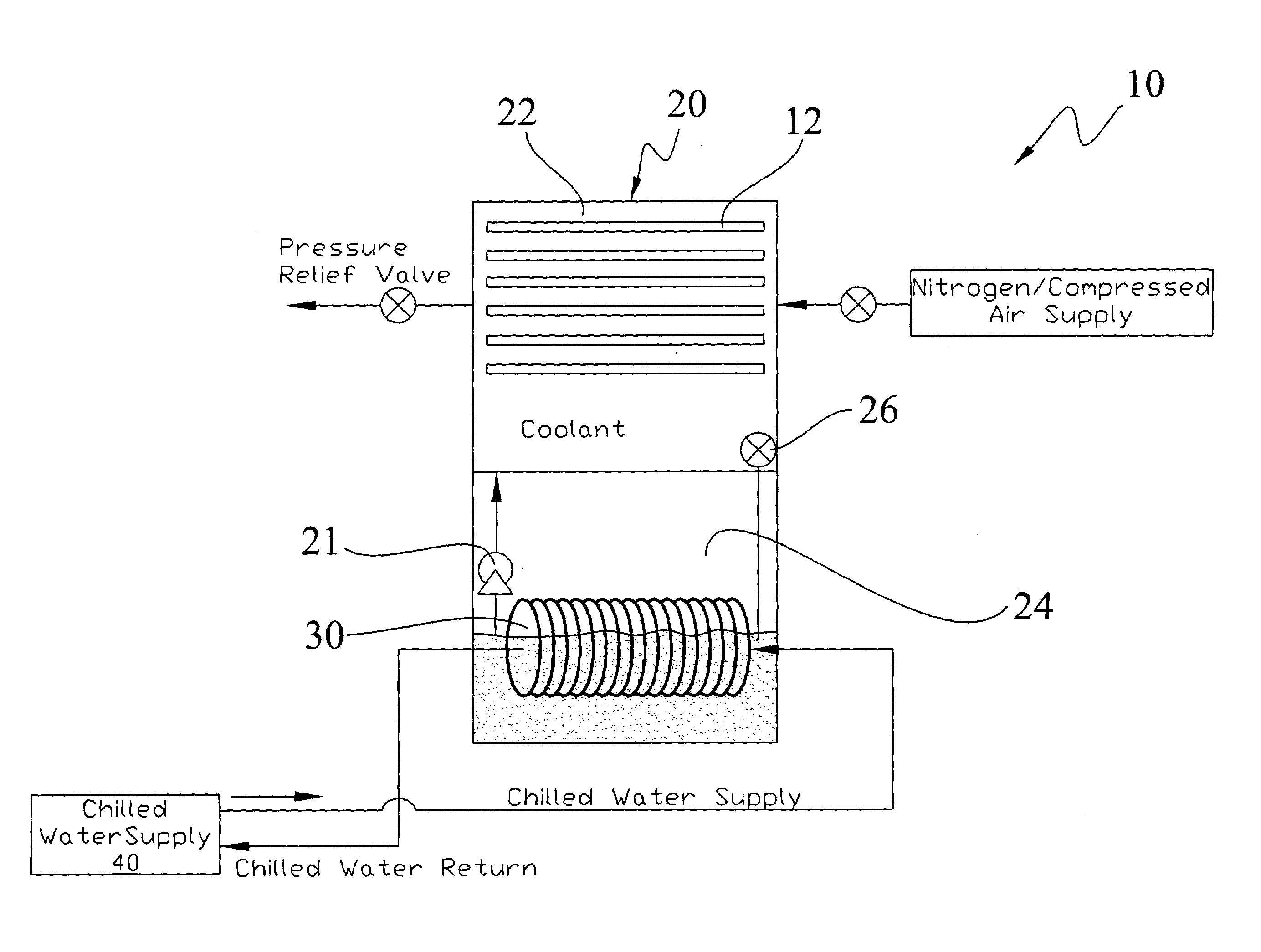
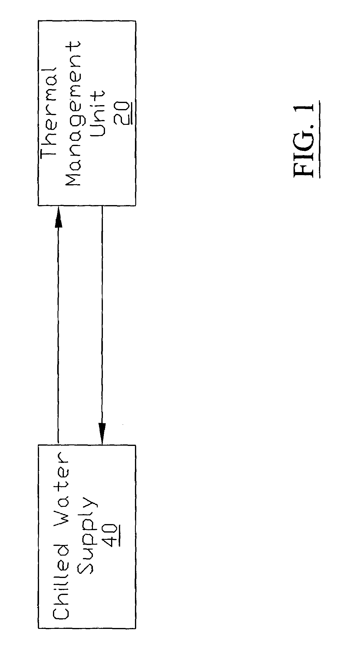
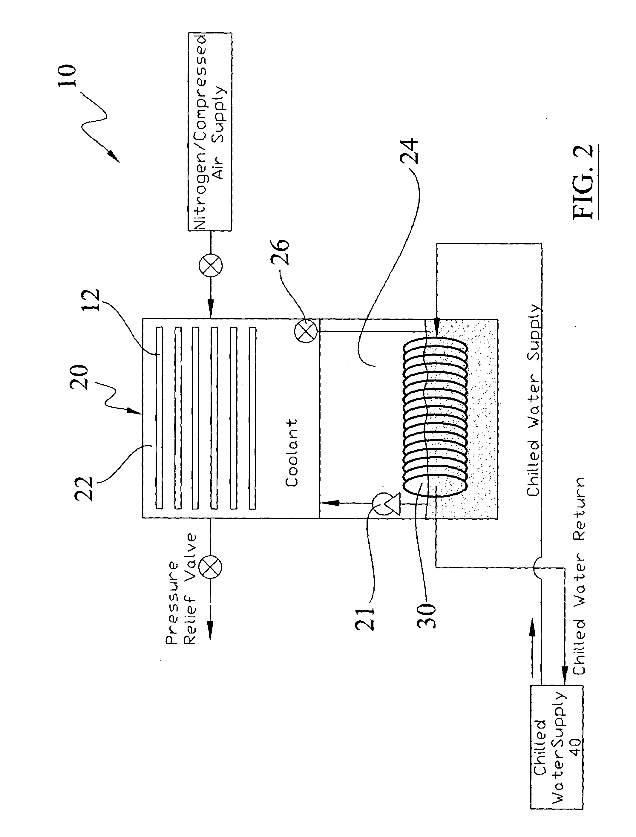
[0037]Turning now descriptively to the drawings, in which similar reference characters denote similar elements throughout the several views, FIGS. 1 through 10 illustrate a coolant recovery system 10, which comprises a thermal management unit 20 having a spray chamber 22 and a coolant recovery chamber 24, a first cooling coil 30 within the coolant recovery chamber 24, and a chilled water supply 40 fluidly connected to the first cooling coil 30. The coolant is sprayed upon the electronic device within the spray chamber 22 and then is collected into the coolant recovery chamber 24 for thermal conditioning. A removable chamber 80 may be removably positioned within the spray chamber 22. In an alternative embodiment, a central unit 50 may be connected to a plurality of thermal management units 20.

B. Thermal Management Unit

[0038]The thermal management unit 20 contains the electronic devices, such as a semiconductor 14, to be thermally managed. The thermal management unit 20 may...


PUM


Abstract

A coolant recovery system for reducing coolant loss within thermal management systems. The coolant recovery system includes a thermal management unit having a spray chamber and a coolant recovery chamber, a first cooling coil within the coolant recovery chamber, and a chilled water supply fluidly connected to the first cooling coil. The coolant is sprayed upon the electronic device within the spray chamber and then is collected into the coolant recovery chamber for thermal conditioning. A removable chamber may be removably positioned within the spray chamber. In an alternative embodiment, a central unit may be connected to a plurality of thermal management units.

Description

CROSS REFERENCE TO RELATED APPLICATIONS[0001]I hereby claim benefit under Title 35, United States Code, Section 120 of U.S. patent application Ser. No. 10 / 243,683 filed Sep. 13, 2002 entitled “Semiconductor Burn-In Thermal Management System”. This application is a continuation-in-part of the Ser. No. 10 / 243,683 application filed on Sep. 13, 2002 now U.S. Pat. No. 6,857,283. The Ser. No. 10 / 243,683 application is hereby incorporated by reference into this application.STATEMENT REGARDING FEDERALLY SPONSORED RESEARCH OR DEVELOPMENT[0002]Not applicable to this application.BACKGROUND OF THE INVENTION[0003]1. Field of the Invention[0004]The present invention relates generally to electronics cooling systems and more specifically it relates to a coolant recovery system for reducing coolant loss within thermal management systems. [0005]2. Description of the Related Art[0006]Thermal management systems for electronic systems have been in use for years. Thermal management systems are used in va...

Claims


Application Information

Patent Timeline
Patent Type & Authority Patents(United States)
IPC IPC(8): G01R31/28G05D23/19
CPCG05D23/1919G01R31/2874H01L23/4735H01L2224/32H01L2924/16152
Inventor CADER, TAHIRTILTON, CHARLES L.TILTON, DONALD D.WOS, GEORGE J.
Owner PARKER INTANGIBLES LLC
Why Eureka
Try Eureka