Electronic pneumatic paintball gun

a paintball gun and pneumatic technology, applied in the field of marking devices, can solve the problems of poor design that is not suitable for electronic automation, complexity, and complexity, and achieve the effects of reducing the overall height of the gun, reducing the effectiveness of the bolt, and reducing the amount of energy

Inactive Publication Date: 2005-05-10
AKALMP
View PDF50 Cites 62 Cited by
  • Summary
  • Abstract
  • Description
  • Claims
  • Application Information

AI Technical Summary

Benefits of technology

[0008]The present invention provides an improved paintball gun which operates at a low internal pressure with minimal distortion and damage to the paintball when fired and increases the effective number of shots peak tank. It is reliable, has a reduced number of parts and is easily maintained. This is accomplished with the use of a simplified pneumatics pressure regulator, hammer system, ram, bolt and electronics. These and other features and advantages of the invention will be more readily apparent upon reading the following description of a preferred embodiment of the invention and upon reference to the accompanying drawings.
[0009]The present preferred embodiment paintball gun utilizes the technology of two existing patents. One is U.S. Pat. No. 5,791,328 (Aaron K. Alexander) which is a paintball gun valve that permits the paintball gun to fire a paintball with the use of air pressure that is much lower than any other paintball gun in use today and to increase the effective number of shots per tank by a factor of 2. All other valves require the use of an average of 300 psi or higher to work. This valve permits the gun to operate normally at 180 psi though, in testing, guns have been operated as low as 100 psi and still maintained the correct velocity of 300 fps on the ball.

Problems solved by technology

The only problem with a closed bolt paintball gun was its complexity, which required a higher price tag.
Instead, electronics have complicated the situation further because many of the paintball guns upon which the electronic guns are based had poor designs that are not suitable for electronic automation.
Four out of five of them are open bolt designs, but they all are inadequate for the job, usually being overly complicated with many small and delicate parts with poor construction.
The electronic guns use electric solenoid valves which are pressure sensitive and easily damaged from the high air pressures often used in prior art paintball guns.
Also the use of the unregulated air to move the bolt back and forth creates a problem when the ball gets caught by the bolt.
The bolt can cut the ball in half causing the gun to stop working.
Some electronic guns have hoses and delicate parts on the outside of the gun that can be hit and damaged by a paintball.

Method used


Image

  • Electronic pneumatic paintball gun
  • Electronic pneumatic paintball gun
  • Electronic pneumatic paintball gun

Examples


Embodiment Construction

[0127]For the purposes of promoting an understanding of the principles of the invention, reference will now be made to the embodiment illustrated in the drawings and specific language will be used to describe the same. It will nevertheless be understood that no limitation of the scope of the invention is thereby intended, and alterations and modifications in the illustrated device, and further applications of the principles of the invention as illustrated therein are herein contemplated as would normally occur to one skilled in the art to which the invention relates.

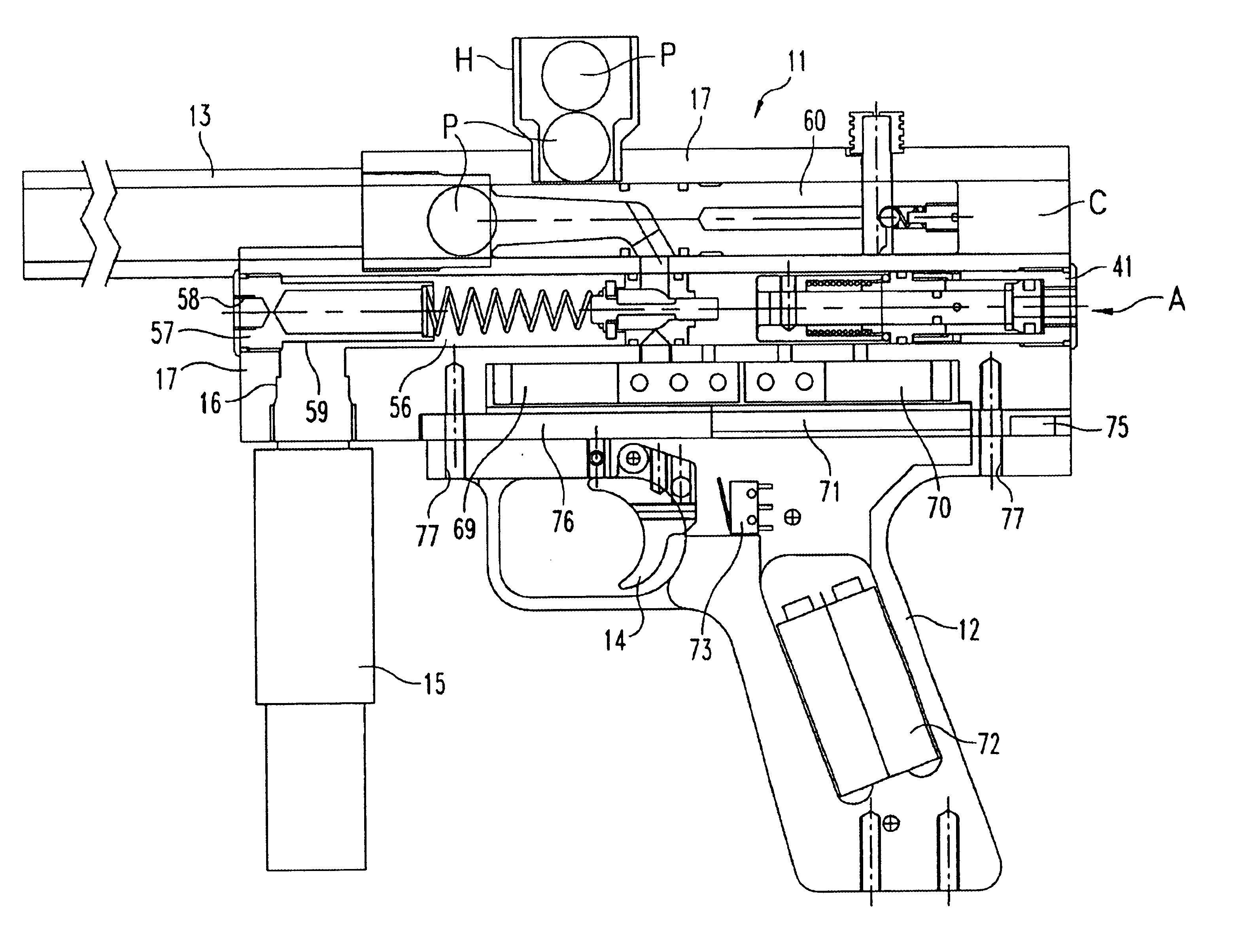
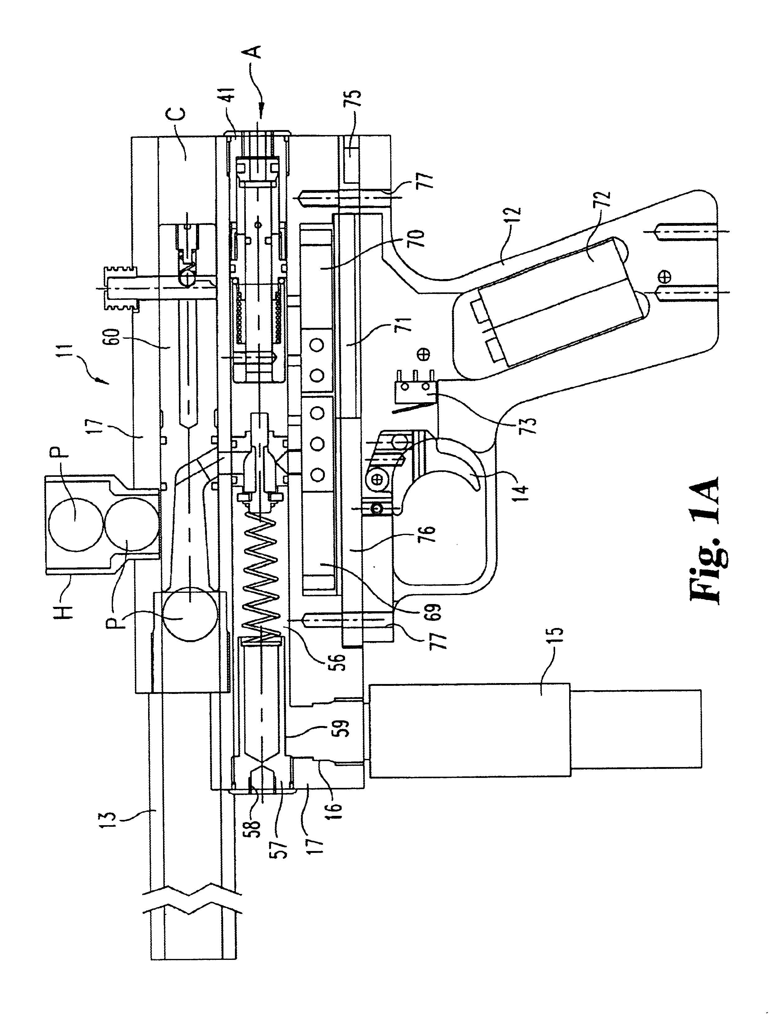
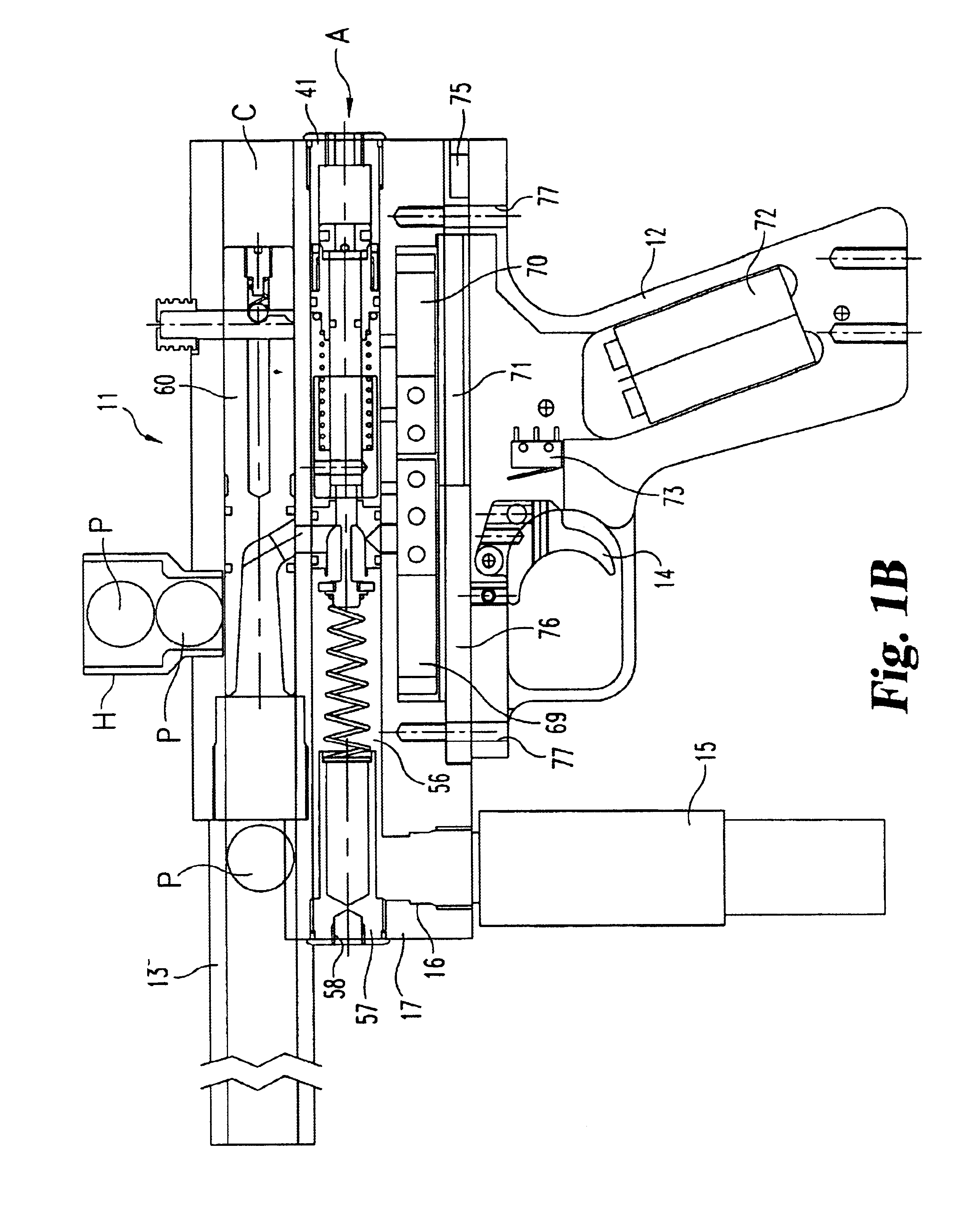
[0128]With reference to FIGS. 1a-e, there are shown left and right side elevational views of a preferred embodiment electronic paintball gun of the present invention, indicated generally at 11. Front and rear end elevational views of the paintball gun 11 are illustrated in FIGS. 2a-b, respectively. The paintball gun 11 includes a gun body 17, preferably formed from extruded aluminum (but which may be formed from any suit...


PUM


Abstract

An improved electronic pneumatic paintball gun, with an improved, simplified design incorporating an improved pneumatic hammer, electronic control circuit, pressure regulator, bolt design and cocking system for utilization in paintball guns or related devices. This paintball gun eliminates complex mechanical systems thus providing a consistent operation with low maintenance. The paintball gun utilizes low pressure to minimize damage to paint balls when fired and to the paintball gun's internal parts, plus increase the effective number of shots per tank.

Description

TECHNICAL FIELD OF THE INVENTION[0001]The present invention generally relates to marking devices and, more particularly, to an electronic pneumatic paintball game.BACKGROUND OF THE INVENTION[0002]The sport of paintball was developed back in the early 1980's. Paintball gun technology has developed rapidly since then, out-pacing all other paintball-related equipment. The evolution of paintball guns started with single shot pistols. Then the pump paintball gun was developed which still had to be manually re-cocked to load another paintball and set the hammer in the “ready-to-fire” position. Pump paintball guns were the standard paintball bun for a few years. Then Tippmann Pneumatics (U.S. Pat. No. 4,819,609) developed one of the first semi-automatic paintball guns. This design used air to push a spring-fired hammer back to the ready position after the gun was fired. This design is known as an open bolt blow back paintball gun because the hammer is blown back into the ready position and...

Claims


Application Information

Patent Timeline
Patent Type & Authority Patents(United States)
IPC IPC(8): F41B11/00F41B11/32F41B11/06F41B11/02F41B11/62
CPCF41B11/52F41B11/57F41B11/723F41B11/724F41B11/722F41B11/62F41B11/71
Inventor ALEXANDER, AARON K.ALEXANDER, LARRY G.
Owner AKALMP
Why Eureka
Try Eureka