Device to discharge liquid steel from a container to a crystallizer with rollers

a technology of liquid steel and crystallizer, which is applied in the field of liquid steel discharge devices, can solve the problems of uneven feed of liquid steel in the meniscus along the generatrix of the roller, turbulence which has a negative effect, and inability to meet the needs of the customer, so as to prevent the collection of inclusions, uniform temperature of liquid steel, and uniform heat exchange

Inactive Publication Date: 2005-05-10
DANIELI & C OFF MEC SPA
View PDF7 Cites 5 Cited by
  • Summary
  • Abstract
  • Description
  • Claims
  • Application Information

AI Technical Summary

Benefits of technology

[0019]The liquid steel is cast into the central compartment of the discharge element through a plurality of holes made in the lower part of the container above (tundish, intermediate tundish, or other type of container) in order to distribute the liquid steel in a uniform manner substantially along the whole length of the central compartment. Then, through the lower apertures of the intermediate walls, the steel substantially divides into two flows for each side: a first flow, once it has passed the corresponding lateral wall from above, is able to feed in a uniform manner the meniscus which is created in the afore-mentioned substantially V-shaped upper space, along the generatrixes of said rollers; and a second flow which is directed downwards through the afore-mentioned discharge apertures and goes directly under the discharge nozzle in order to make the temperature of the liquid steel uniform and to prevent the collection of inclusions. In this way we also obtain the advantage that the feed of liquid steel is all uniform, because the steel overflows uniformly over the outer wall of the discharge element and then goes to feed the meniscus.
[0020]The lateral walls of the discharge element are able to remain preferably a few millimeters below the level of the meniscus, thus ensuring a substantially flat meniscus without turbulence.
[0021]Such a uniform distribution of the liquid steel in the zone of the meniscus, along the generatrix of the rollers, ensures uniform heat exchange and uniform solidification, thus preventing cracks from occurring on the surface of the cast product.
[0022]Inside the central compartment of the discharge element there are elements able to reduce the kinetic energy of the liquid steel arriving from the tundish.

Problems solved by technology

In such continuous casting machines, one of the main problems is the need to form, in the substantially V-shaped compartment which is created between the two rollers, a meniscus of liquid steel which is possibly uniform and homogeneous.
In such conventional devices, there is no guarantee that the meniscus will be homogeneous and uniform, since the liquid steel is discharged directly into the bath which forms the meniscus, with the kinetic energy appropriate to the different level of the tundish and the crystallizer; the result is turbulence which has a negative affect especially in the zones of the meniscus wherein the contact occurs between the liquid steel and the rollers and / or the lateral containing plates.
The main disadvantage of this known device is that the steel is fed onto the meniscus discontinuously, by means of the eyelets which are made on the lateral wall of the SEN.
Consequently the feed of the liquid steel in the meniscus along the generatrix of the roller is not uniform.
The SEN described in this known device, which does not use a roller-type crystallizer, is not able to feed the liquid steel along the meniscus in a uniform manner.
This device has the following disadvantages: when there are high quantity flows of liquid steel it increases the turbulence thereof, because all the steel goes directly on the meniscus; it is not able to make the temperature of the liquid steel uniform in the liquid pool of the crystallizer, between the two rollers; it can create, under the SEN, a dead zone where the liquid steel stagnates and where inclusions can collect, which compromise the quality of the cast strip.

Method used


Image

  • Device to discharge liquid steel from a container to a crystallizer with rollers
  • Device to discharge liquid steel from a container to a crystallizer with rollers
  • Device to discharge liquid steel from a container to a crystallizer with rollers

Examples


Embodiment Construction

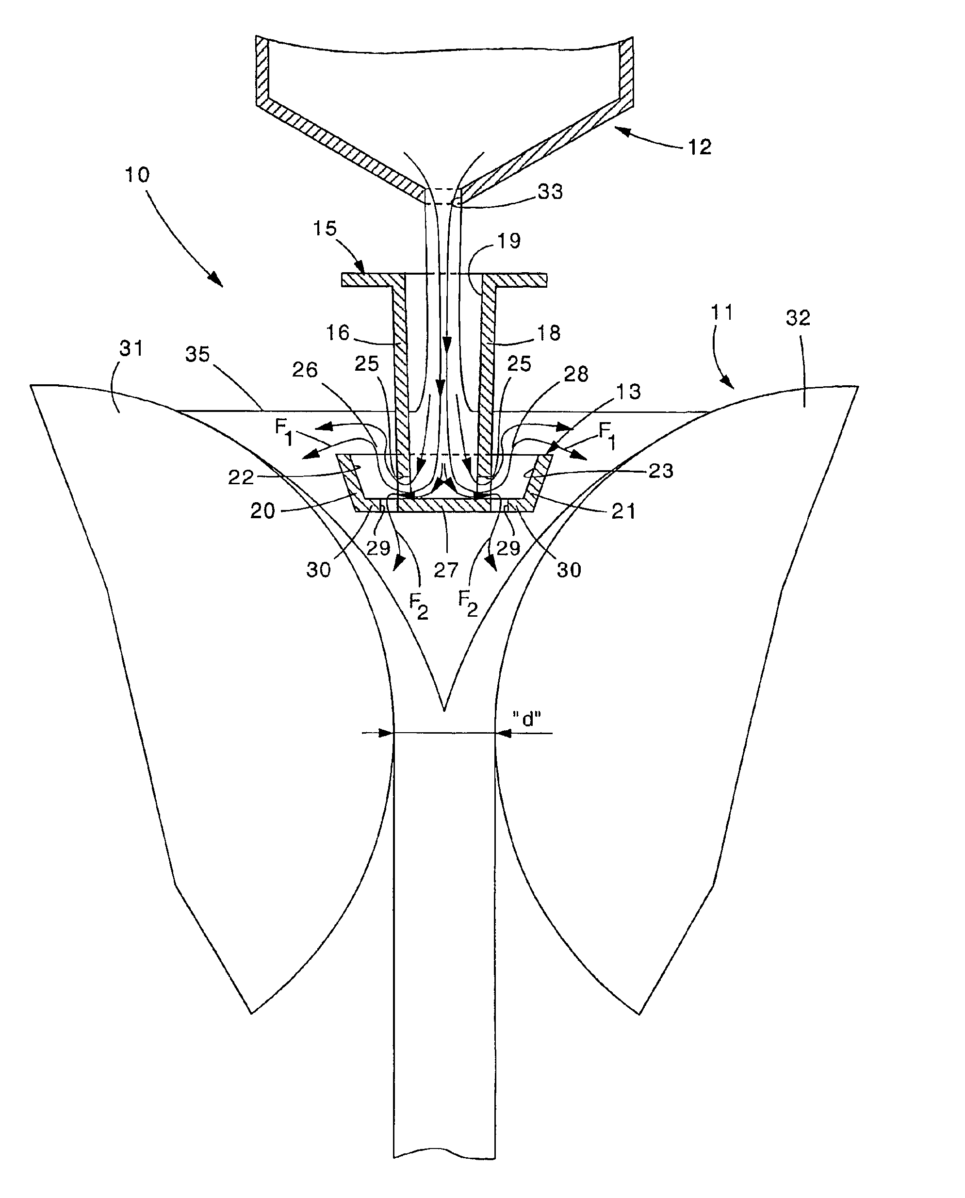
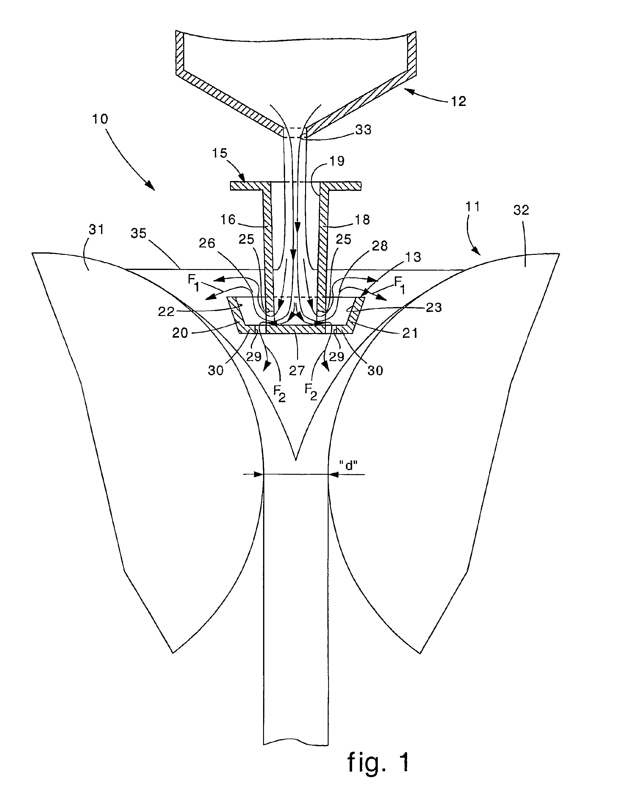
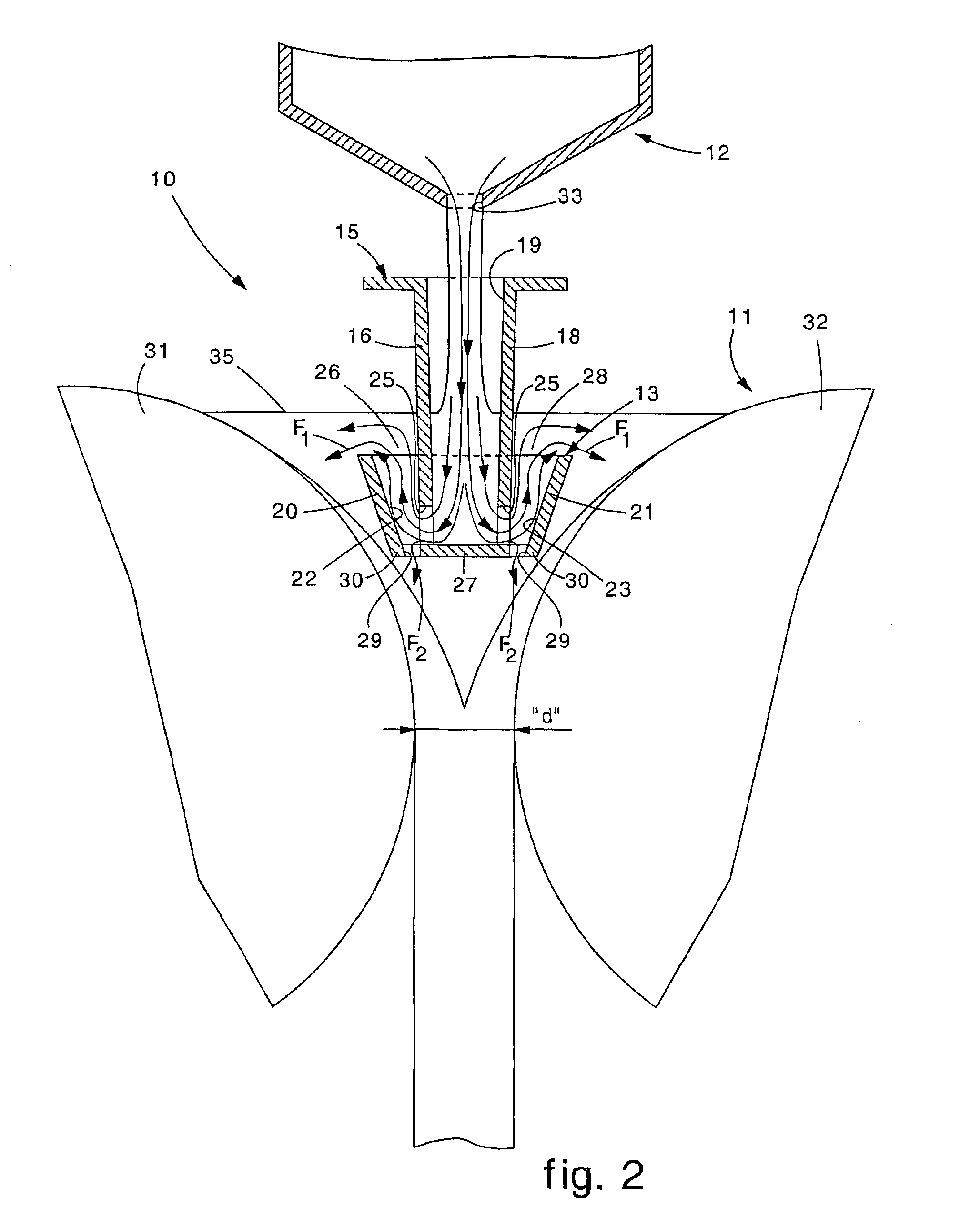
[0039]With reference to FIGS. 1, 2, 3, 4 and 5, a device 10 according to the invention to discharge the liquid steel contained in a container 12 into a crystallizer 11 of the type with two rollers 31 and 32, comprises a nozzle of the submerged type, or SEN, 13.

[0040]The container 12, arranged upstream of the crystallizer 11, is not essential for the purposes of the present invention and can comprise a conventional tundish, an intermediate tundish or any other type of container.

[0041]The SEN 13 is shaped so as to define a main tank 15, with a substantially rectangular longitudinal shape, provided with vertical intermediate walls 16 and 18 which define a central compartment 19 and lateral walls 20 and 21 which, with the vertical intermediate walls 16 and 18, define two lateral compartments 22 and 23 communicating with the central compartment 19 by means of apertures 25 made in the lower part of the vertical intermediate walls 16 and 18.

[0042]The lateral walls or wings 20 and 21 are lo...


PUM

PropertyMeasurementUnit
diameteraaaaaaaaaa
diameteraaaaaaaaaa
speedaaaaaaaaaa

Abstract

Device (10) to discharge liquid steel from a container (12) to a crystallizer (11) with rollers (31, 32), formed by a discharge element (13) arranged between the container (12) and the rollers (31, 32), wherein the discharge element (13) is shaped so as to define a main tank (15) provided with vertical intermediate walls (16, 18) which define a central compartment (19) into which the liquid steel is able to be cast from the container (12). Lateral walls (20, 21) define two lateral compartments (22, 23) communicating with the central compartment (19) by means of apertures (25) made in the lower part of the vertical intermediate walls (16, 18). On the bottom wall (27) of the discharge element (13), between the intermediate walls (16, 18) and the lateral walls (20, 21), discharge apertures (29) are provided through which the cast steel is able to flow downwards. Moreover guide elements (30) are provided at the sides of the discharge apertures (29).

Description

CROSS-REFERENCE TO RELATED APPLICATION[0001]This application is a 371 of PCT / IB02 / 01269 filed on Apr. 18, 2002.FIELD OF THE INVENTION[0002]The invention refers to a device to discharge the liquid steel contained in a container, consisting for example of a tundish, into the roller-type crystallizer of a continuous casting machine for strip. To be more exact, the discharge device is able to form a uniform meniscus between the rollers which define the crystallizer. Between the tundish and the discharge device an intermediate or secondary tundish can be arranged, in which the liquid steel arriving from the tundish is contained before being transferred to the roller-type crystallizer below.BACKGROUND OF THE INVENTION[0003]The state of the art includes continuous casting machines for steel strip, or similar products, wherein the crystallizer consists substantially of two rollers, which are arranged between lateral containing walls and rotate in opposite directions to convey the liquid ste...

Claims


Application Information

Patent Timeline
Patent Type & Authority Patents(United States)
IPC IPC(8): B22D11/06
CPCB22D11/0642
Inventor POLONI, ALFREDOKAPAJ, NUREDIN
Owner DANIELI & C OFF MEC SPA
Why Eureka
Try Eureka