Thermal analysis in a data processing system

a data processing system and thermal analysis technology, applied in the field of data processing systems, can solve the problems of pdus and switches consuming valuable rack sidewall space, power consumption and cooling to become much more critical, and it is difficult to determine which cables attach where,

Inactive Publication Date: 2005-05-10
IBM CORP
View PDF17 Cites 100 Cited by
  • Summary
  • Abstract
  • Description
  • Claims
  • Application Information

AI Technical Summary

Problems solved by technology

These systems enable organizations to reap many benefits of consolidation, however each server requires its own infrastructure including cables for power, Ethernet, systems management, power distribution units (PDUs), keyboard / video / mouse (KVM) switches and Fibre Channel switches, which offer challenges of their own.
For instance, a rack of 42 1U servers can have hundreds of cables strung throughout the rack, making it difficult to determine which cables attach where and complicating the installation and removal of servers from the rack.
Further, the PDUs and switches consume valuable rack sidewall space.
The compactness of systems like blade servers forces otherwise independent servers to share a thermal profile with hardware resources, including enclosures, power supplies, fans, and management hardware, causing power consumption and cooling to become much more critical.
Because of the large number of elements housed within blade servers, the airflow and heating patterns within the blade servers are fairly complicated and many possible sources of thermal problems can exist, exacerbating the detrimental effects and maintenance involved with thermal crises and thermal problems that can lead to thermal crises.
A thermal crisis is a situation where a monitored temperature within a thermal system like an enclosure of an electronic system or an element in the electronic system has reached a critical threshold beyond which the equipment should not be operated.
A thermal crisis may result from a number of different situations, among them are overheating of an electrical component within the enclosure; partial or total failure of a cooling fan within the enclosure; failure of the room heating, ventilation, and air conditioning (HVAC) equipment; inadequate cooling in the facility (e.g., overcrowded machine room); airflow blocked by an outside obstruction (e.g., close proximity to a wall or materials draped in front of air intakes); removal (without replacement) of an enclosure panel or subsystem (resulting in redirected airflow within the enclosure); and over-configuration (i.e., violation of enclosure specifications regarding limitations for some configurations).

Method used


Image

  • Thermal analysis in a data processing system
  • Thermal analysis in a data processing system
  • Thermal analysis in a data processing system

Examples


Embodiment Construction

[0016]The following is a detailed description of example embodiments of the invention depicted in the accompanying drawings. The example embodiments are in such detail as to clearly communicate the invention. However, the amount of detail offered is not intended to limit the anticipated variations of embodiments, but on the contrary, the intention is to cover all modifications, equivalents, and alternatives falling within the spirit and scope of the present invention as defined by the appended claims. The detailed descriptions below are designed to make such embodiments obvious to a person of ordinary skill in the art.

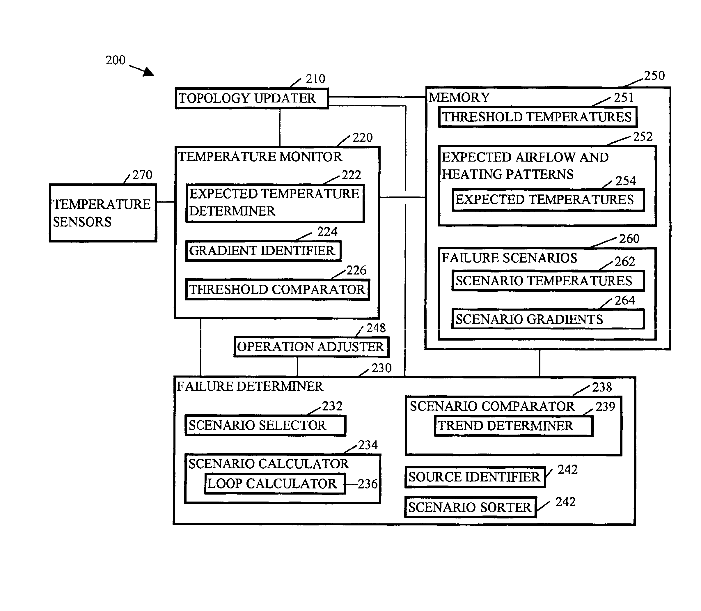
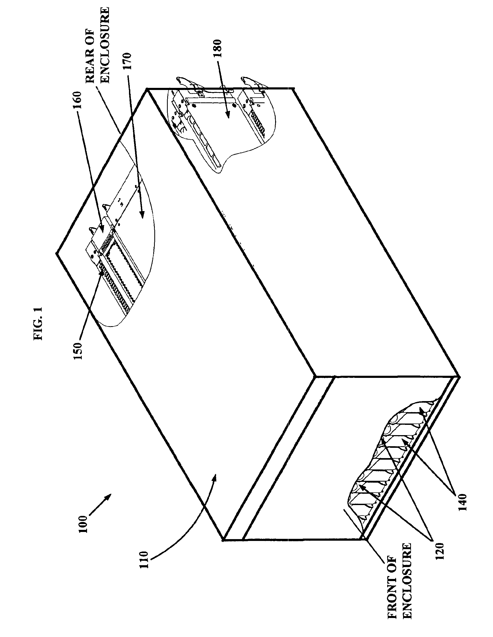
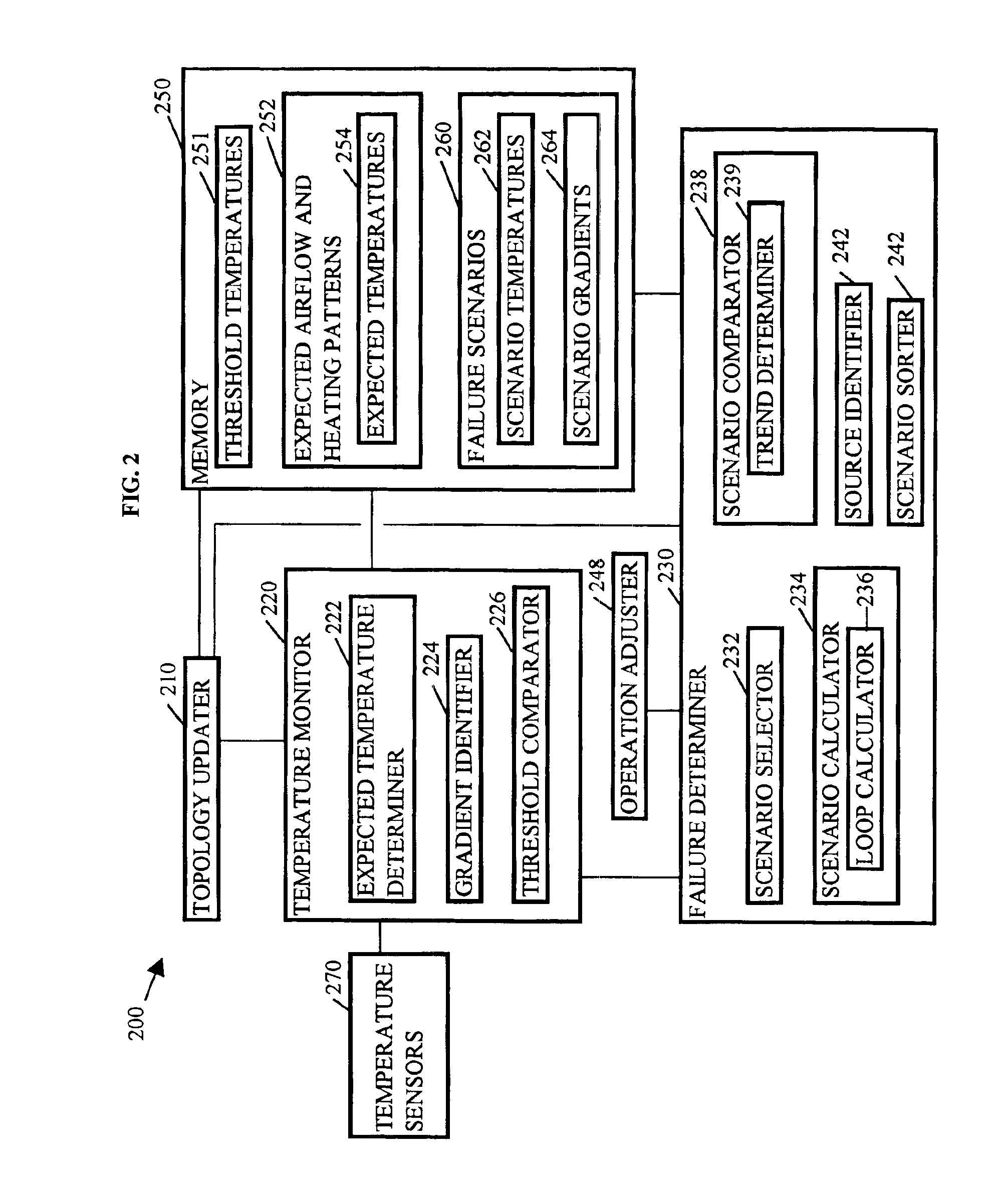
[0017]Generally speaking, automated, user-friendly methods, systems, and media for thermal analysis of an electronic system are contemplated. The electronic system includes a number of elements having interrelated airflow and heating patterns. In particular, the elements may be servers, power supplies, blowers, switches, management controller, panels and the ventilatio...


PUM


Abstract

Methods, systems, and media for thermal analysis are disclosed. Embodiments of the invention receive temperatures associated with elements of a system. The temperatures received are dependant upon airflow and heating patterns of the elements. Differences between the temperatures received and expected temperatures are detected. Potential airflow and heating patterns associated with a thermal problem are then determined, the potential airflow and heating patterns being substantially consistent with the temperatures received, to identify a root cause of the thermal problem as a probable source of the differences. More specifically, embodiments collect temperature readings from temperature sensors within an enclosure of the system; identify and upward temperature gradient or temperature that exceeds a threshold temperature; and select a failure scenario associated with a root cause of a thermal problem that is similar to the thermal problem described by the temperature readings collected.

Description

FIELD OF INVENTION[0001]The present invention relates to the field of data processing systems and more particularly to methods and systems for handling thermal energy generated by data processing systems.BACKGROUND[0002]Many organizations have begun consolidating servers into centralized data centers, looking to use physical, application or data consolidation as a means of reducing the challenges and costs associated with administering many small servers scattered across the enterprise. To date, physical consolidation has generally involved replacing bulky tower servers with slender 1U or 2U rack systems. The slender rack systems take less space and put the servers and infrastructure within easy reach of the administrator, rather than spread across a large campus. These systems enable organizations to reap many benefits of consolidation, however each server requires its own infrastructure including cables for power, Ethernet, systems management, power distribution units (PDUs), keyb...

Claims


Application Information

Patent Timeline
Patent Type & Authority Patents(United States)
IPC IPC(8): F24F11/00G06F1/20G05B23/02G06F11/30
CPCF24F11/006G06F1/206G06F11/3006G05B23/0235G06F11/3058H05K7/20727H05K7/20836G06F11/3051F24F2011/0052F24F11/30F24F11/32F24F11/62F24F11/52
Inventor CRIPPEN, MARTIN JOSEPHMATTESON, JASON AARONPIAZZA, WILLIAM JOSEPH
Owner IBM CORP
Why Eureka
Try Eureka