
Structural cockpit window and method of making same

a cockpit window and structural technology, applied in the field of structural cockpit windows, can solve the problems of difficult implementation of materials, difficult to meet the requirements of aircraft, so as to reduce the weight and cost of the window assembly, and eliminate the manufacturing steps of framing and bolting

Inactive Publication Date: 2005-05-10
THE BOEING CO
View PDF13 Cites 56 Cited by
  • Summary
  • Abstract
  • Description
  • Claims
  • Application Information

AI Technical Summary

Benefits of technology

The patent describes a window for a mobile platform that is made up of three layers of transparent fiberglass and a layer of transparent epoxy. The window is integrated with the composite skin of the platform, which eliminates the need for separate framing and bolting steps, reducing weight and cost. The window is also protected from wear and tear by a removable glass outer-pane. The technical effect of this invention is a window that is lightweight, cost-effective, and easy to replace.

Problems solved by technology

For example, glass, while hard and resistant to abrasion, is brittle and heavy.
And transparent polymers, such as acrylic and polycarbonate, while lightweight and easily formed into complex shapes, are relatively weak compared to glass.
Yet even with their limitations, both materials are commonly used in aircraft industry.
However, there remain some challenges to implementing these materials in the manufacture of aircraft cockpit windows.
While this type of window assembly with a window coupled to a metal frame has served very well in the past, the metal frame remains a relatively heavy component.

Method used


Image

  • Structural cockpit window and method of making same
  • Structural cockpit window and method of making same
  • Structural cockpit window and method of making same

Examples


Embodiment Construction

[0012]The following description of the preferred embodiment(s) is merely exemplary in nature and is in no way intended to limit the invention, its application, or uses.

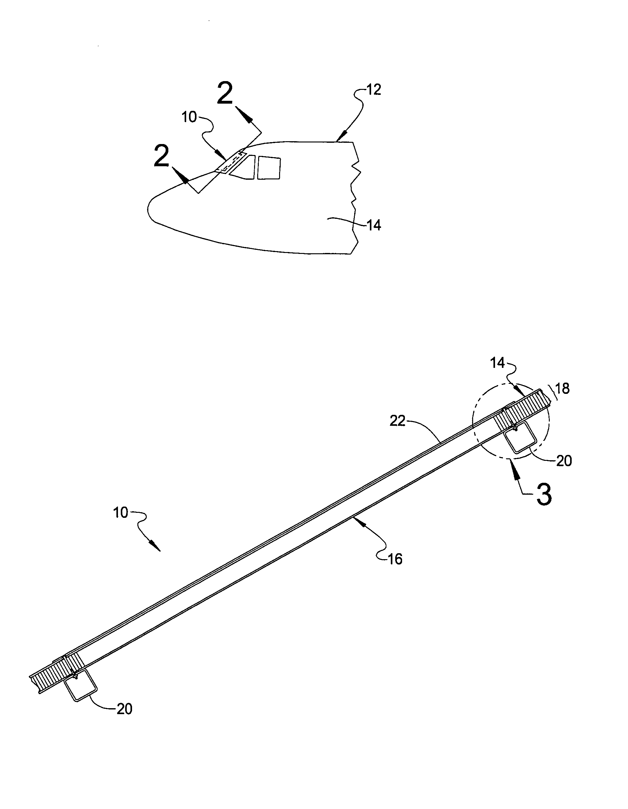
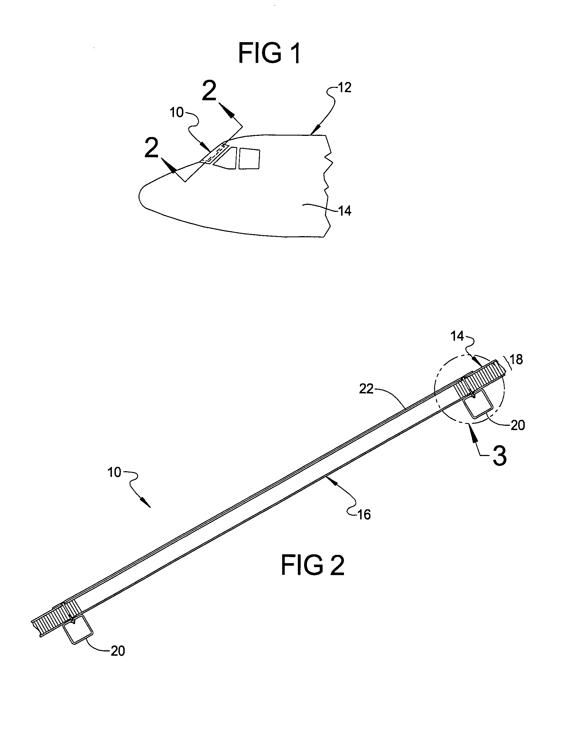
[0013]Referring to FIG. 1, there is illustrated a window assembly 10 constructed according to the principles of the present invention shown mounted to an aircraft 12. While in the particular example provided the window assembly 10 is illustrated as a cockpit window, it is to be understood that the window assembly 10 may be used in any number of aircraft applications including side viewing windows, canopies, or any other area of an aircraft requiring structurally strong transparent ports for allowing viewing therethrough. The aircraft 12 has a skin 14 surrounding the window assembly 10. The aircraft skin 14 is a plastic skin reinforced with fibers, for example carbon fibers, as will be described in greater detail below.

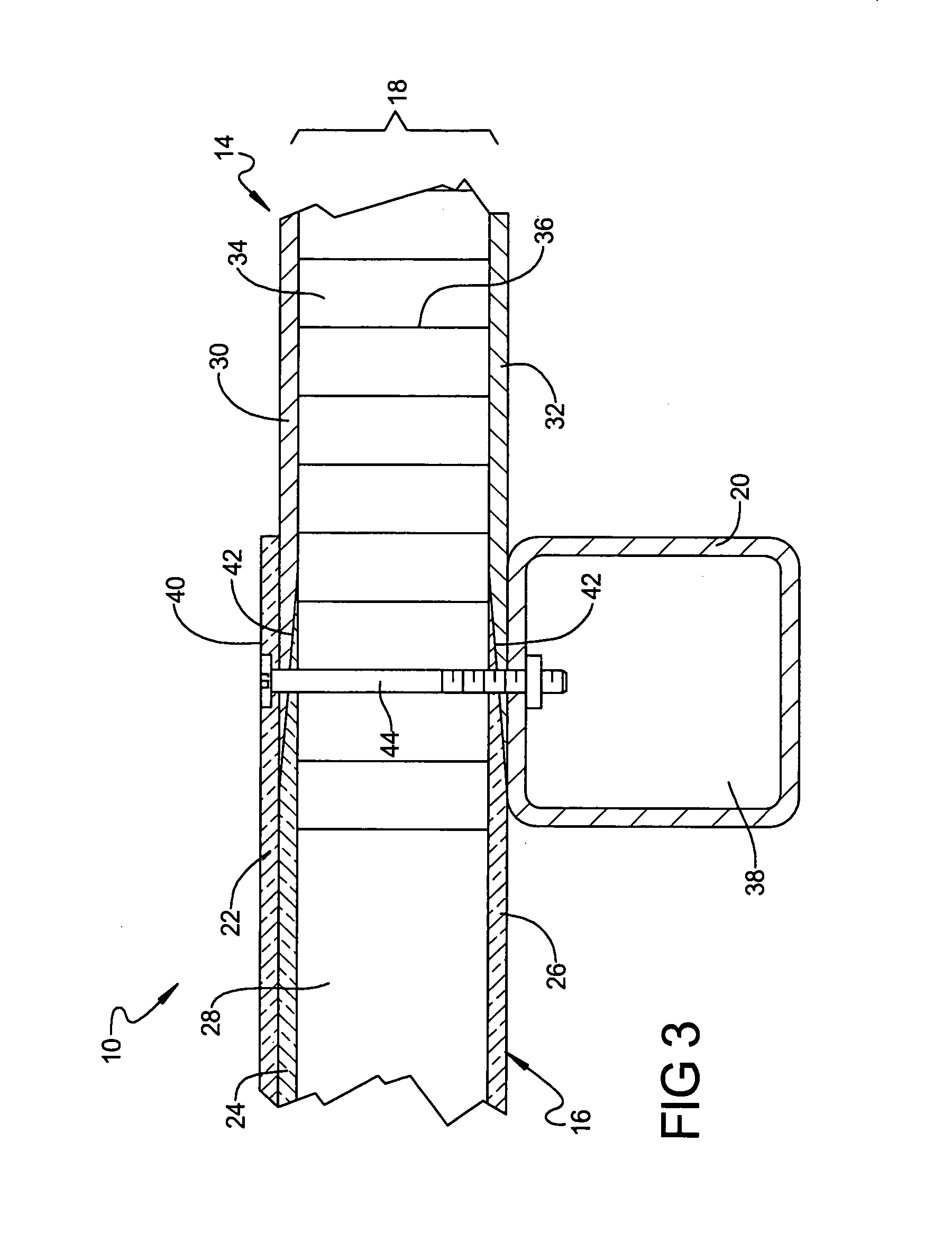
[0014]With reference to FIG. 2, the window assembly 10 generally includes a window 16, a transition p...


PUM

PropertyMeasurementUnit
transparentaaaaaaaaaa
index of refractionaaaaaaaaaa
refraction indexaaaaaaaaaa

Abstract

A window adapted to be integrally formed with a skin of an aircraft having a first transparent fiberglass layer, a second transparent fiberglass layer, and a transparent epoxy layer. The transparent epoxy layer is located between the first and second transparent fiberglass layers. A glass outer-pane is removably coupled to the first transparent fiberglass layer such that the glass outer-pane covers the first transparent fiberglass layer. The first and second transparent fiberglass layers have an index of refraction approximately matching an index of refraction of the transparent epoxy layer. The first and second transparent fiberglass layers are adapted to be integrally formed with the skin of the aircraft.

Description

FIELD OF THE INVENTION[0001]The present invention relates to aircraft cockpit windows and more particularly to an aircraft structural cockpit window integrally formed with the skin of the aircraft.BACKGROUND OF THE INVENTION[0002]Conventional aircraft windows and canopies have traditionally been formed while trying to balance considerations of weight, strength, durability, and cost. Various materials have been employed in an attempt to find an optimal balance. For example, glass, while hard and resistant to abrasion, is brittle and heavy. And transparent polymers, such as acrylic and polycarbonate, while lightweight and easily formed into complex shapes, are relatively weak compared to glass. Yet even with their limitations, both materials are commonly used in aircraft industry. A more recent innovation, transparent composite materials, offer the strength of glass with the lighter weight of polymers and are becoming more common within the industry. However, there remain some challen...

Claims


Application Information

Patent Timeline
Patent Type & Authority Patents(United States)
IPC IPC(8): B29C70/10B29C70/20B64C1/00B64C1/14B29C70/08
CPCB29C70/086B64C1/1492Y02T50/433Y02T50/40B29C70/20
Inventor NORDMAN, PAUL S.
Owner THE BOEING CO
Learn More