

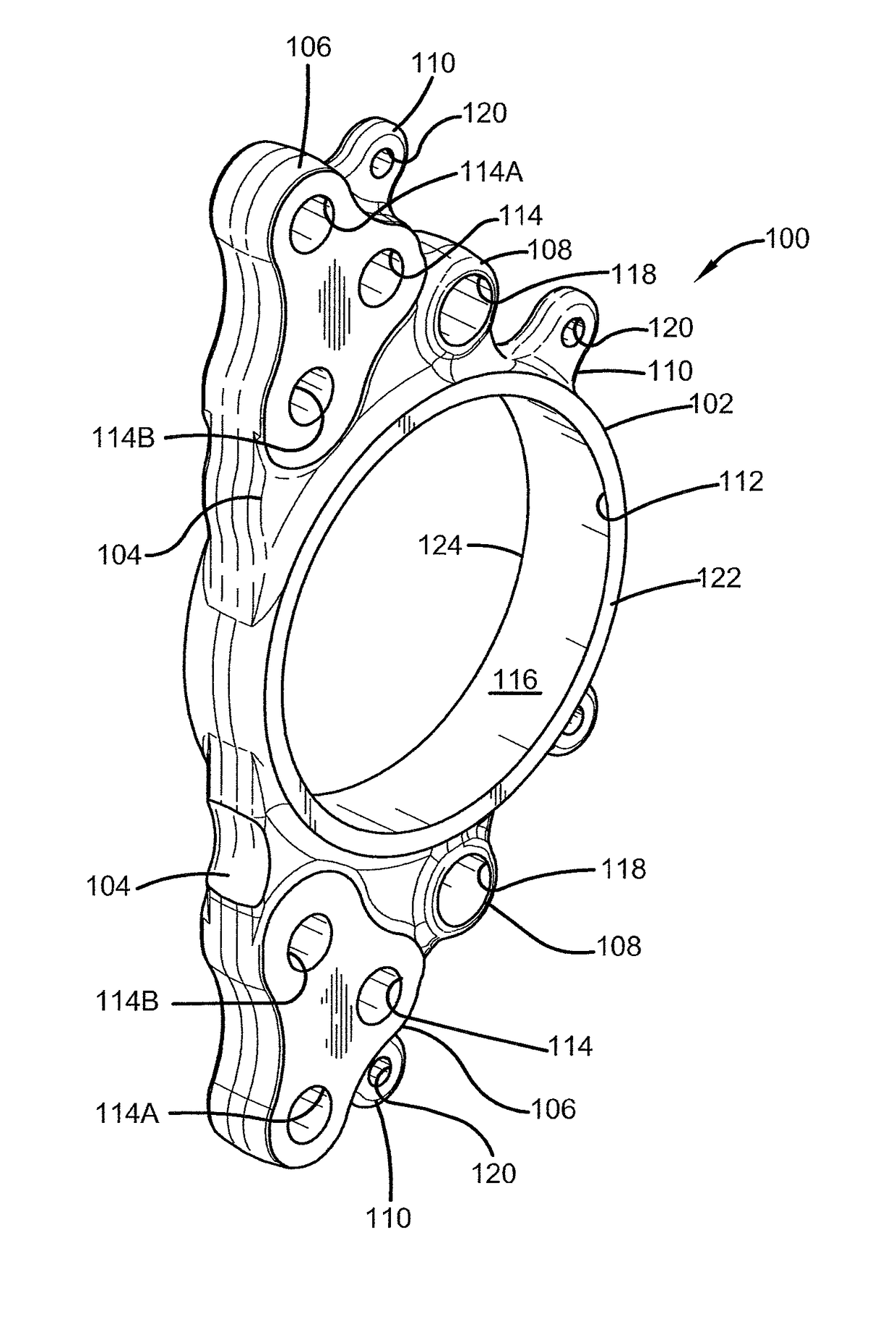
Torque plate for heavy-duty vehicles
a technology for disc brake systems and torque plates, which is applied in the direction of brake types, slack adjusters, braking elements, etc., can solve the problems of inability to meet the requirements of the vehicle, etc., to achieve the effect of reducing size and structural features, and reducing diameter
- Summary
- Abstract
- Description
- Claims
- Application Information
AI Technical Summary
Benefits of technology
Problems solved by technology
Method used
Image

Examples
Embodiment Construction
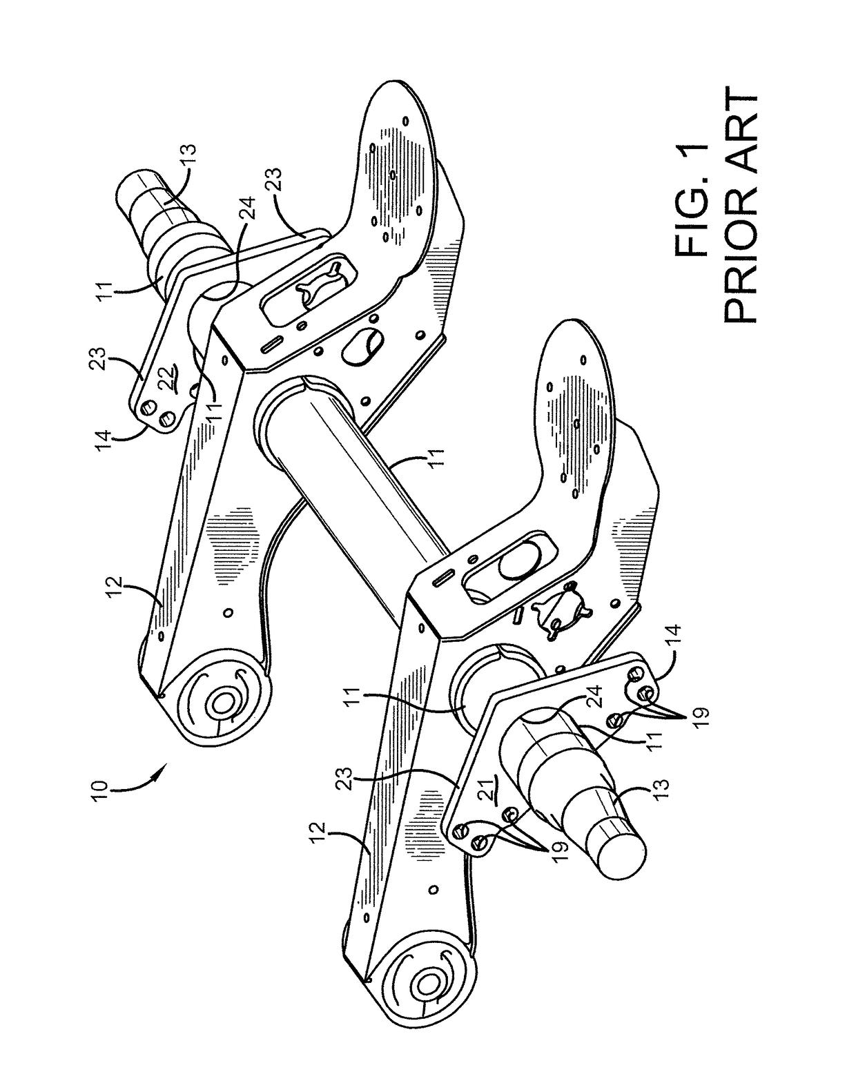
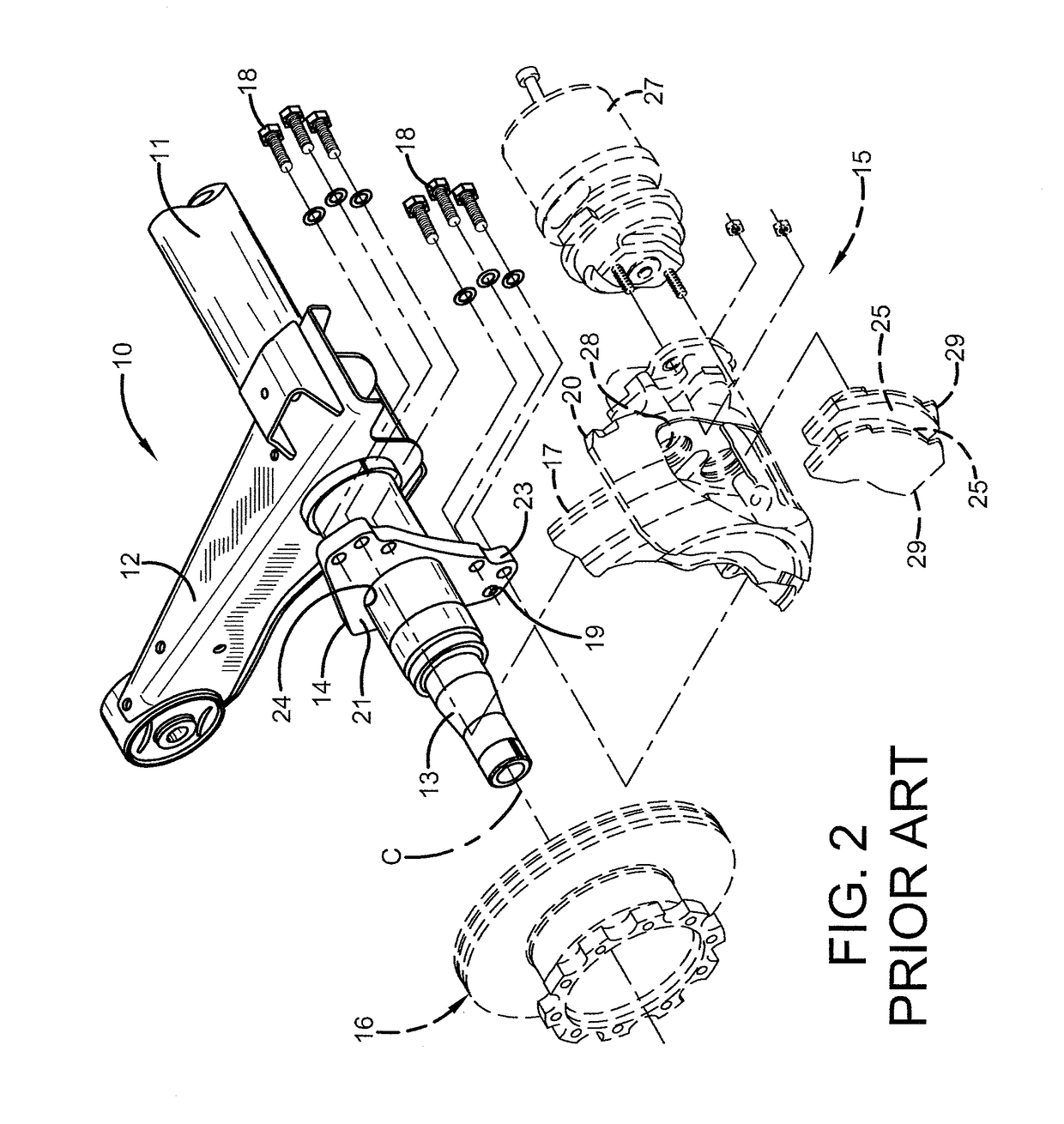
[0030]In order to better understand the improved torque plate for heavy-duty vehicles of the present invention and the environment in which it operates, a prior art torque plate for heavy-duty vehicles 14 is shown in FIGS. 1 and 2, and now will be described. A trailing arm axle / suspension system of the type useful with the present invention is indicated at 10. Axle / suspension system 10 is of a type commonly known in the art and includes an axle tube 11, a pair of trailing arms 12, a pair of axle spindles 13, and a pair of prior art torque plates 14. A pair of brake assemblies 15 (only one shown) is mounted on axle / suspension system 10, and will be described in greater detail below. Unless otherwise noted, all components of axle / suspension system 10 typically are formed of a durable metal such as steel.
[0031]Each one of the pair of trailing arms 12 is spaced apart along axle tube 11 and is rigidly attached thereto by a method well known in the art such as welding. Similarly, each one...
PUM
 Abstract
Description
Claims
Application Information