
Positive air system for inkjet print head

a technology of inkjet print head and air system, which is applied in the direction of printing, inking apparatus, other printing apparatus, etc., can solve the problems of high potential for dust and debris to disrupt or interfere with printing operation,

Inactive Publication Date: 2005-05-10
ILLINOIS TOOL WORKS INC
View PDF16 Cites 36 Cited by
  • Summary
  • Abstract
  • Description
  • Claims
  • Application Information

AI Technical Summary

Benefits of technology

[0007]A positive air system, for a fluid jetting device that jets a fluid in a fluid droplet path prevents the ingress of dust and debris to the fluid jetting device and further prevents the introduction of dust and debris into the fluid droplet path.
[0008]The air system is configured to reduce the potential for dust and debris interfering with the jetting pattern. The system further forces debris from an article that is to have the jetted fluid applied thereto. Such a system provides an envelope of the local print head environment and around the jetted fluid to prevent the ingress of outside dust and debris into the local environment.
[0014]Alternately, the positive air system includes an air knife having a pressurized air reservoir. An air inlet provides air to the reservoir and a restricted pressurized air outlet provides an exit for the air. The air outlet is formed to direct a stream of pressurized air therefrom in a direction that diverges from the fluid droplet path. In this manner, the fluid droplet path and the pressurized air stream direction do not converge. The pressurized air flowing from the outlet prevents the ingress of dust and debris to the fluid jetting device and further prevents the introduction of dust and debris into the fluid droplet path, and wherein the pressurized air flowing from the orifices does not interfere with the fluid moving through the droplet path.

Problems solved by technology

In that many such operations are carried out in commercial or industrial environments the processes are potentially subjected to dust and debris.
To this end, the potential for dust and debris to disrupt or interfere with the printing operation is quite high.
As such, they are relatively costly, and cannot be retrofitted to existing inkjet system.
These high pressure systems can adversely effect printing by action of the high pressure air interfering with the ink droplet pattern.
Most desirably, such a system minimally, if at all, adversely interferes with the jetted fluid.

Method used


Image

  • Positive air system for inkjet print head
  • Positive air system for inkjet print head
  • Positive air system for inkjet print head

Examples


embodiment 28

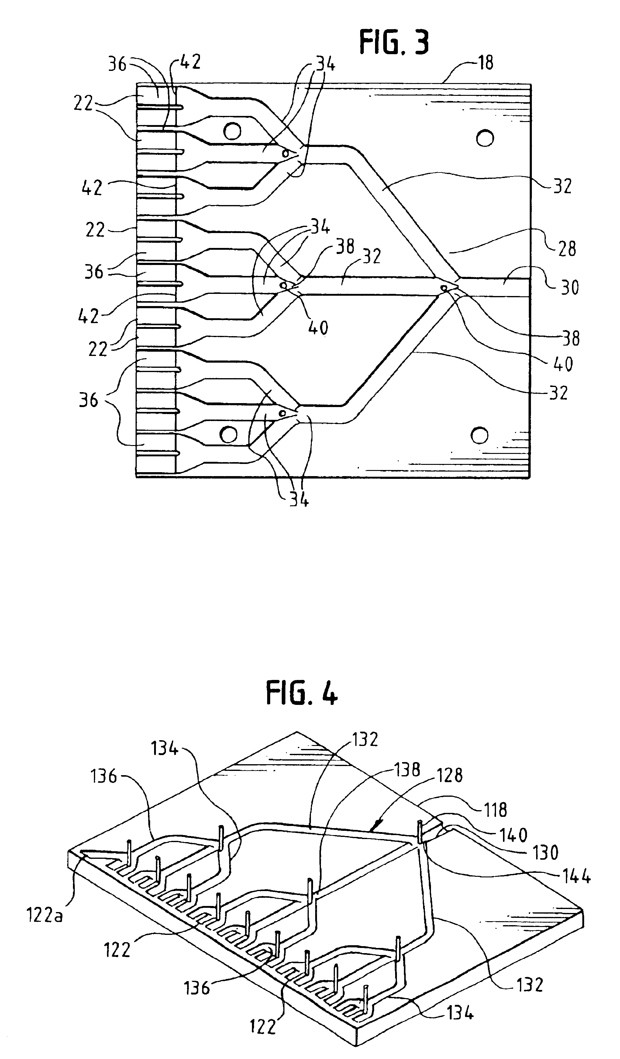
[0047]An alternate embodiment of an air path 128 for an air knife 18 is shown in FIG. 4. In this embodiment, the air path 128 is formed different from that of the embodiment 28 in FIG. 3. The path 128 includes a main or primary branch 130 that divides into three secondary branches 132. Each of the three secondary branches 132 in turn divides into three tertiary branches 134 which in turn divide into three orifice feed branches 136. Again, pins 140, diverters 138 and restrictors 142 can be used (if desired) to facilitate the balancing or equalizing or air pressure at each of the orifices 122. Additionally, a restriction 144 (as a decrease in diameter or a restrictor) can be formed at about the primary branch 130 to further facilitate pressure balancing.

[0048]As seen in FIG. 4, the orifices 122a at about the edge of the knife 118 can be angled outward. In this manner (because the knives 118 are angled outward and / or upward relative to the print head 10, as best seen in FIGS. 10-13), a...

embodiment 118

[0052]Similar to the angled orifices 122a of the embodiment 118 illustrated in FIG. 4, the spacer plate 330 can have an angled edge (as indicated at 333) to direct air outwardly, at an angle, to account for the angled orientation of the knives 318. This prevents “gaps” at the corners or junctures of the upper and side knives 318.

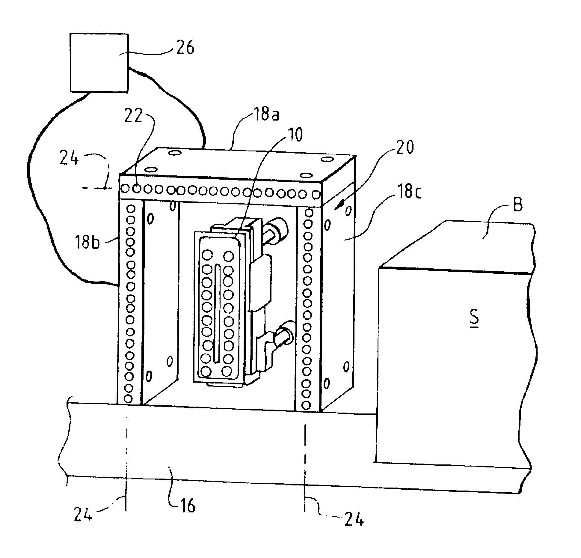
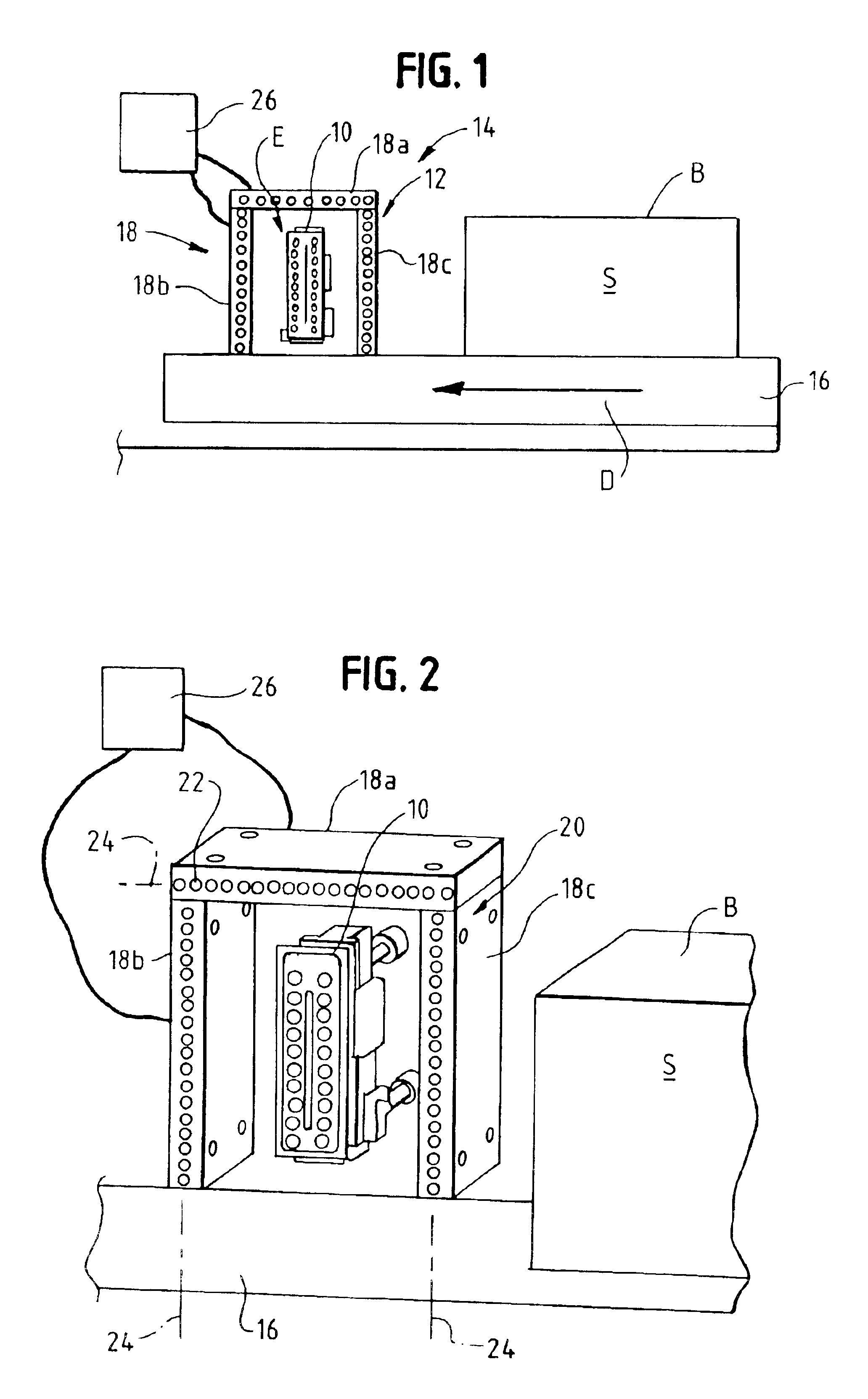
[0053]In conjunction with the novel use of a low pressure system, as seen in FIG. 10, the present positive air system 12 uses angled curtains or knives 18 to facilitate directing the deflected air away (indicated by the arrow at 44 in FIG. 8) from the print head 10. That is, rather than the orifices 22, 122, 222 (or slots 228, 322) directing air perpendicular to the box surface S onto which the indicia is printed, the orifices 22, 122, 222 (or slots 228, 322) direct the air at an angle relative to the surface S. In this manner, the air that deflects off of the surface S is directed away from the print head 10, rather than toward the print head 10. It has bee...


PUM


Abstract

A positive air system, for a fluid jetting device that jets a fluid in a fluid droplet path prevents the ingress of dust and debris to the fluid jetting device and further prevents the introduction of dust and debris into the fluid droplet path. The air system includes an enclosure having at least one wall defining a barrier and enclosing the fluid jetting device. The barrier defines a local environment. The at least one wall has a plurality of orifices formed therein that are configured to direct a stream of pressurized air therefrom in a direction that diverges from the fluid droplet path. The fluid droplet path and the pressurized air stream direction do not converge so that the pressurized air flowing from the orifices does not interfere with the fluid moving through the droplet path.

Description

BACKGROUND OF THE INVENTION[0001]The present invention relates generally to air systems for fluid jet devices. More particularly, the present invention pertains to air systems to prevent debris from interfering with the proper operation of fluid jet devices, such as ink jet print systems.[0002]Fluid jet devices are in wide spread use. One particular use for such devices is in ink jet printers. There area number of principle types of ink jet printers. One type of printer relies upon capillary action to move a working fluid (e.g., ink) to the print head. The ink is directed from the print head through one or more orifices toward a target substrate. Ink jet printers include an actuator for urging the ink through the orifice. Actuators can include piezzo electric elements, thermal devices and the like. An exemplary ink jet print head is disclosed in DeYoung et al., U.S. Pat. No. 4,418,355.[0003]The ink is ejected from the print head as a droplet of fluid. These droplets are extremely sm...

Claims


Application Information

Patent Timeline
Patent Type & Authority Patents(United States)
IPC IPC(8): B41J2/14B41J2/04B41J2/01
CPCB41J2/04B41J29/12B41J2/14B41J2202/02
Inventor MYHILL, GREGORY A.TAMARIN, CHARLES S.VINCENT, GLEN
Owner ILLINOIS TOOL WORKS INC
Features
  • Generate Ideas
  • Intellectual Property
  • Life Sciences
  • Materials
  • Tech Scout
  • Unparalleled Data Quality
  • Higher Quality Content
  • 60% Fewer Hallucinations
Learn More