Adjustable screed system

a screed system and height adjustment technology, applied in temporary pavings, roads, construction, etc., can solve the problems of insufficient matching of the height of the main and extension screeds, time-consuming and inefficient trial and error approach, and uneven surface of the asphalt ma

Inactive Publication Date: 2005-05-10
CALDER BROS CORP
View PDF14 Cites 31 Cited by
  • Summary
  • Abstract
  • Description
  • Claims
  • Application Information

AI Technical Summary

Benefits of technology

[0017]Yet another object of the present invention is to provide an adjustable screed system having a mechanical link between a main screed and an extension screed for allowing simultaneous adjustment of both the main and extension screeds.
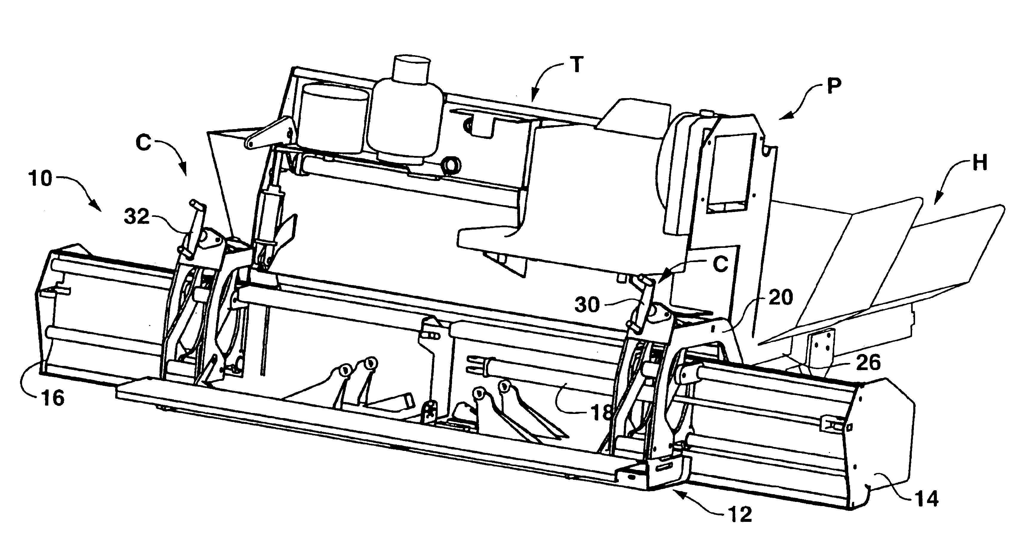
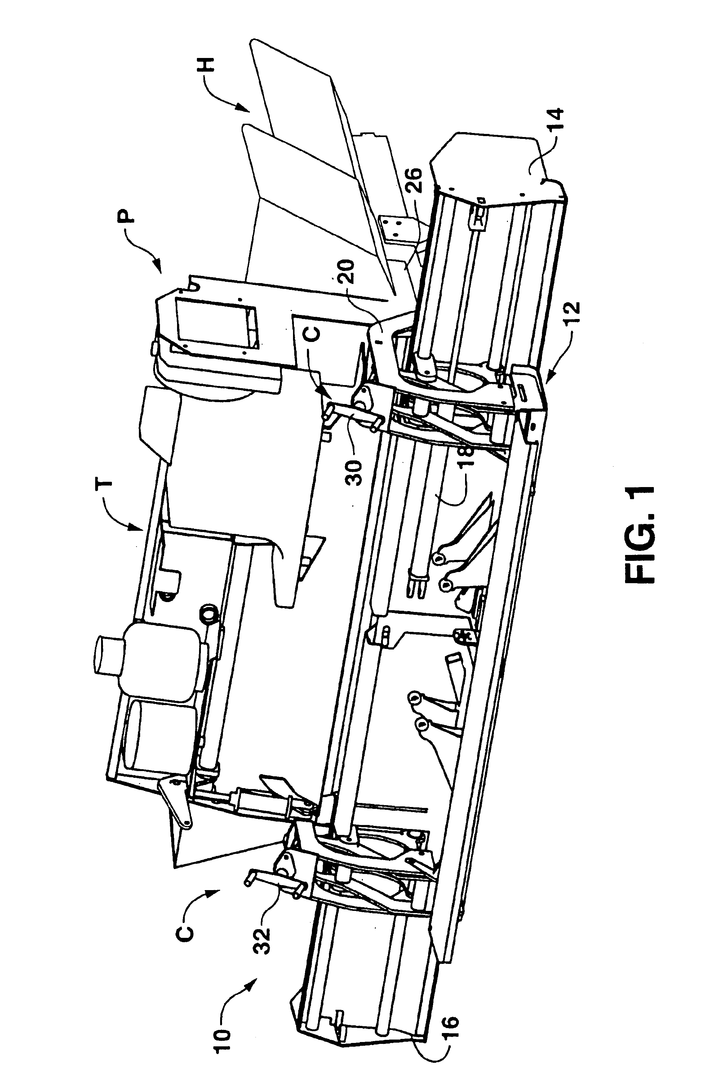
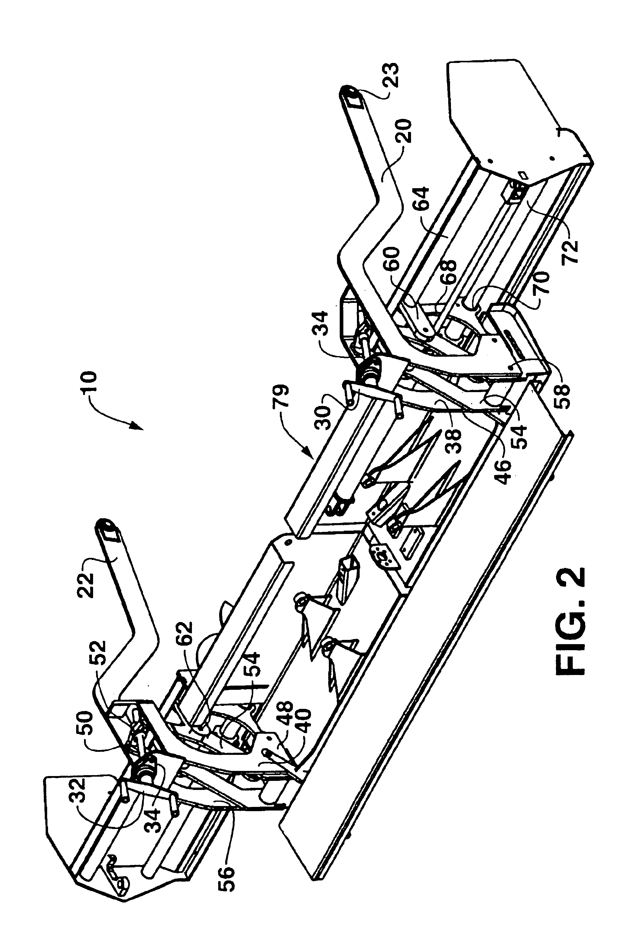
[0021]The present invention includes, in a preferred embodiment, a mechanical linkage having a geometry designed to substantially hold the plane of the main screed and the plane of an extension screed at a generally constant relative angle with respect to one another through a predetermined range of screed depth adjustments. The linkage is configured to allow the extension screed to be raised and lowered by an amount sufficient to compensate for attack angle and elevation changes in the main screed. In particular, the linkage compensates for the effect of the radial distance differences from the axis of rotation of the tow bars (connected to the tractor) of the main screed and extension screed as the main screed pivots around the tow point of the tow bars for different asphalt mat depths.

Problems solved by technology

This step is undesirable in that it results in an overall asphalt mat having a height difference in the surface thereof.
This may result in a trial and error approach which can be time consuming and inefficient.
Thus, the operator of the paver must constantly closely monitor the paving operation, and often times the matching of the mat heights for the main and extension screeds is performed inadequately.

Method used


Image

  • Adjustable screed system
  • Adjustable screed system
  • Adjustable screed system

Examples


example

[0047]FIG. 7 illustrates certain example dimensions of one preferred embodiment of the present invention, for a screed system 10 constructed of steel and weighing of approximately lbs, such dimensions shown in tabular form below:

[0048]

ReferenceDimensionCharacterIn Inchesa6.02b12.00c7.55d7.57e14.50f1.00g7.25h12.00i8.25j8.20k6.02l8.25

[0049]FIG. 8 illustrates dimensions for the same embodiment shown in FIG. 7, except that in the FIG. 8 illustration, the angle of attack of screeds 12, 14 is substantially zero.

[0050]

ReferenceDimensionCharacterIn Inchesa′6.028b′12.000c′7.550d′5.750e′14.250f′1.000g′7.250h′12.000i′8.250j′8.22k′6.028l′8.250

[0051]While the foregoing examples set forth specific dimensions of components of the present invention, it is to be understood that the present invention is not to be limited to such embodiment and dimensions, and that the present invention could be in a variety of other configurations, in accordance with the teachings and disclosure of the invention here...


PUM


Abstract

A mechanical linkage having a geometry designed to substantially hold the plane of a main screed and the plane of an extension screed at a generally constant relative angle with respect to one another through a predetermined range of screed depth adjustments. The linkage is configured to allow the extension screed to be raised and lowered by an amount sufficient to compensate for angle of attack and elevation changes in the main screed. In particular, the linkage compensates for the effect of the radial distance differences from the axis of rotation of tow bars of the main screed and extension screed as the main screed pivots with respect to the tow point of the tow bars for different asphalt mat depths. An alternate embodiment includes actuators, together with sensors, for sensing the position of the extension screed with respect to the main screed and automatically compensating for changes in main screed position to properly orient the extension screed with respect to the main screed.

Description

[0001]This application claims benefit of U.S. Provisional application Ser. No. 60 / 353,079, filed Jan. 30, 2002, the entirety of the disclosure of which is incorporated herein by reference thereto.BACKGROUND OF THE INVENTION[0002]The present invention relates to a system for adjusting an auxiliary, or, extension, screed of a paving machine with respect to a main screed.[0003]In conventional asphalt paving operations, a self-propelled vehicle, known as a “tractor” is used having a hopper on the front end thereof. This hopper receives asphalt paving material, typically from a dump truck, and the tractor generally engages and pushes the truck forwardly as the truck empties its contents into the hopper.[0004]The asphalt material is transferred from the hopper to the roadbed or other surface being paved, and the asphalt empties onto the roadbed in front of transversely extending screw augers. These augers transport the asphalt material laterally in front of an elongated plate, or “screed”...

Claims


Application Information

Patent Timeline
Patent Type & Authority Patents(United States)
IPC IPC(8): E01C19/22E01C19/42
CPCE01C19/42E01C2301/16
Inventor CALDER, WAYNE D.CALDER, DAVID M.
Owner CALDER BROS CORP
Why Eureka
Try Eureka