
Caching of intra-layer calculations for rapid rigorous coupled-wave analyses

a coupled-wave analysis and intra-layer calculation technology, applied in the field of cached intra-layer calculations for rapid rigorous coupled-wave analysis, can solve the problems of inability to provide profile information, difficult, if not impossible, to achieve vertical sidewalls, etc., and achieve the effect of reducing the computation time of rigorous coupled-wave analysis

Inactive Publication Date: 2005-05-10
TOKYO ELECTRON US HOLDINGS INC
View PDF8 Cites 214 Cited by
  • Summary
  • Abstract
  • Description
  • Claims
  • Application Information

AI Technical Summary

Benefits of technology

This approach significantly reduces the computation time required for metrology of periodic structures, enabling faster and more accurate analysis of diffraction data, thereby improving the efficiency and performance of profile measurements.

Problems solved by technology

However, due to limits in current fabrication technologies, vertical sidewalls are difficult, if not impossible, to achieve, and sloping sidewalls are common.
The method is however limited to planar surfaces.
While this is a non-destructive test, it does not provide profile information, but yields only a single number to characterize the quality of the process.
While numerous non-destructive techniques have been suggested for linewidth measurements, such as the scanning electron microscope (SEM) and optical microscope, none of them have the ability to provide complete profile information.
There exist cross-sectional profile metrology tools, such as the atomic force microscope (AFM) and the transmission electron microscope, that provide profile information, but at the cost of being either prohibitively slow or destructive.
Further disadvantages include that these techniques cannot be implemented in-line or in-situ.
This non-uniqueness reduces robustness and accuracy of the results.
However, it is well known that modeling of the diffraction of electromagnetic radiation from periodic structures is a complex problem that requires sophisticated techniques.
Closed analytic solutions are restricted to geometries which are so simple that they are of little interest, and current numerical techniques generally require a prohibitive amount of computation time.
However, using an accurate method such as RCWA, the computation time can be prohibitively long.

Method used


Image

  • Caching of intra-layer calculations for rapid rigorous coupled-wave analyses
  • Caching of intra-layer calculations for rapid rigorous coupled-wave analyses
  • Caching of intra-layer calculations for rapid rigorous coupled-wave analyses

Examples


Embodiment Construction

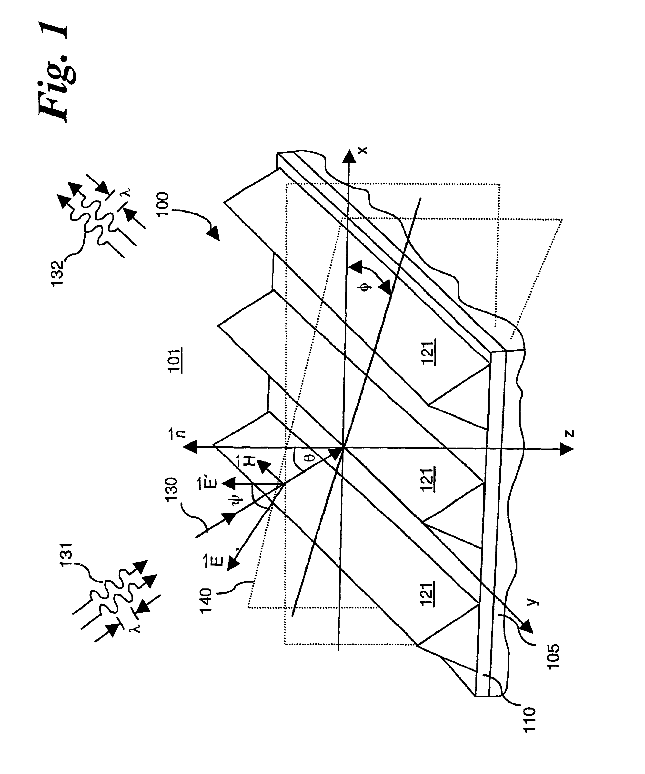
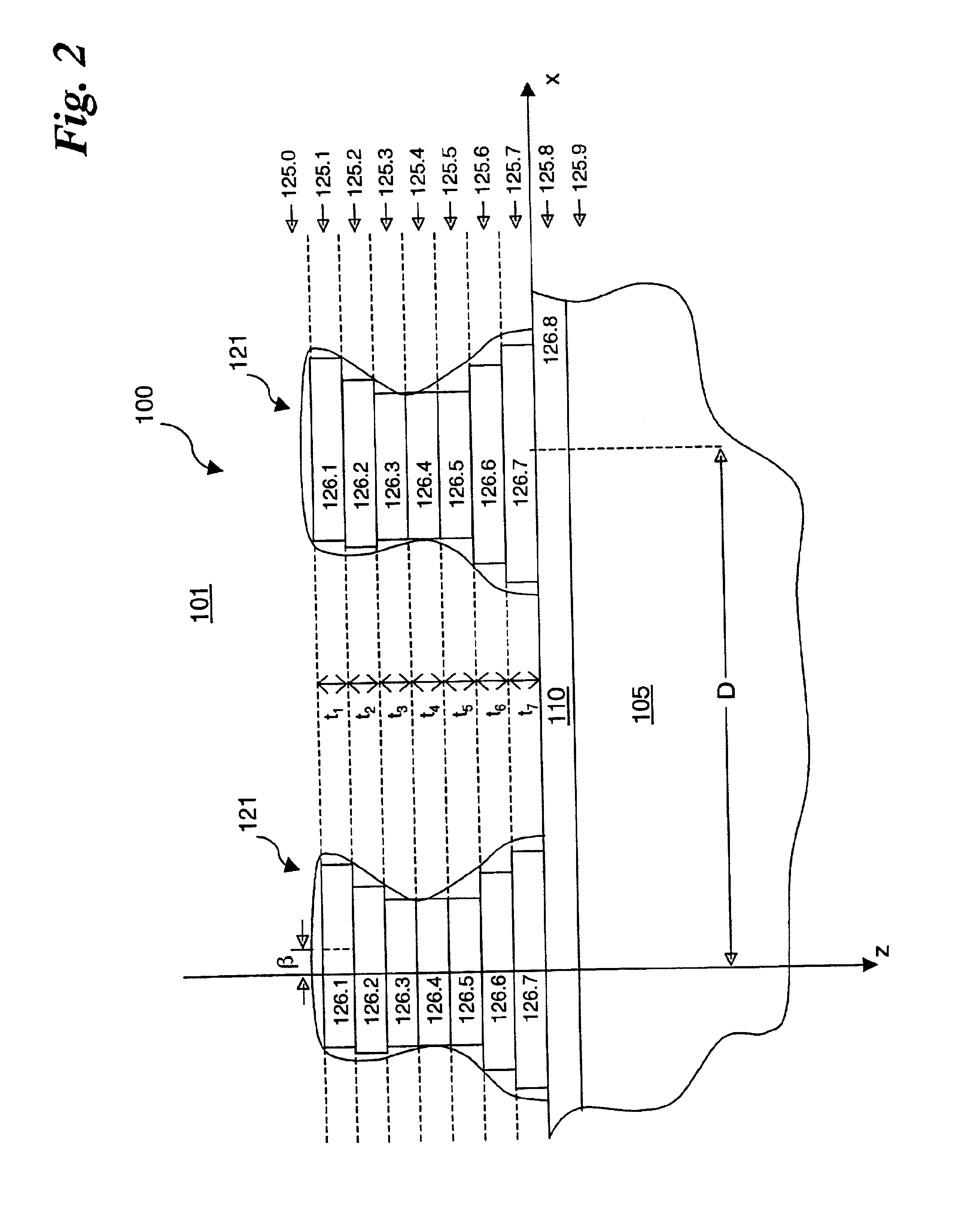
[0034]The method and apparatus of the present invention dramatically improves the performance and efficiency for metrology of profiles of one-dimensionally or two-dimensionally repeating, regularly-spaced series of structures, by reducing the computation time required for RCWA computations by pre-processing and caching intra-layer information and incident-radiation information, and using the cached intra-layer and incident-radiation information for RCWA calculations.

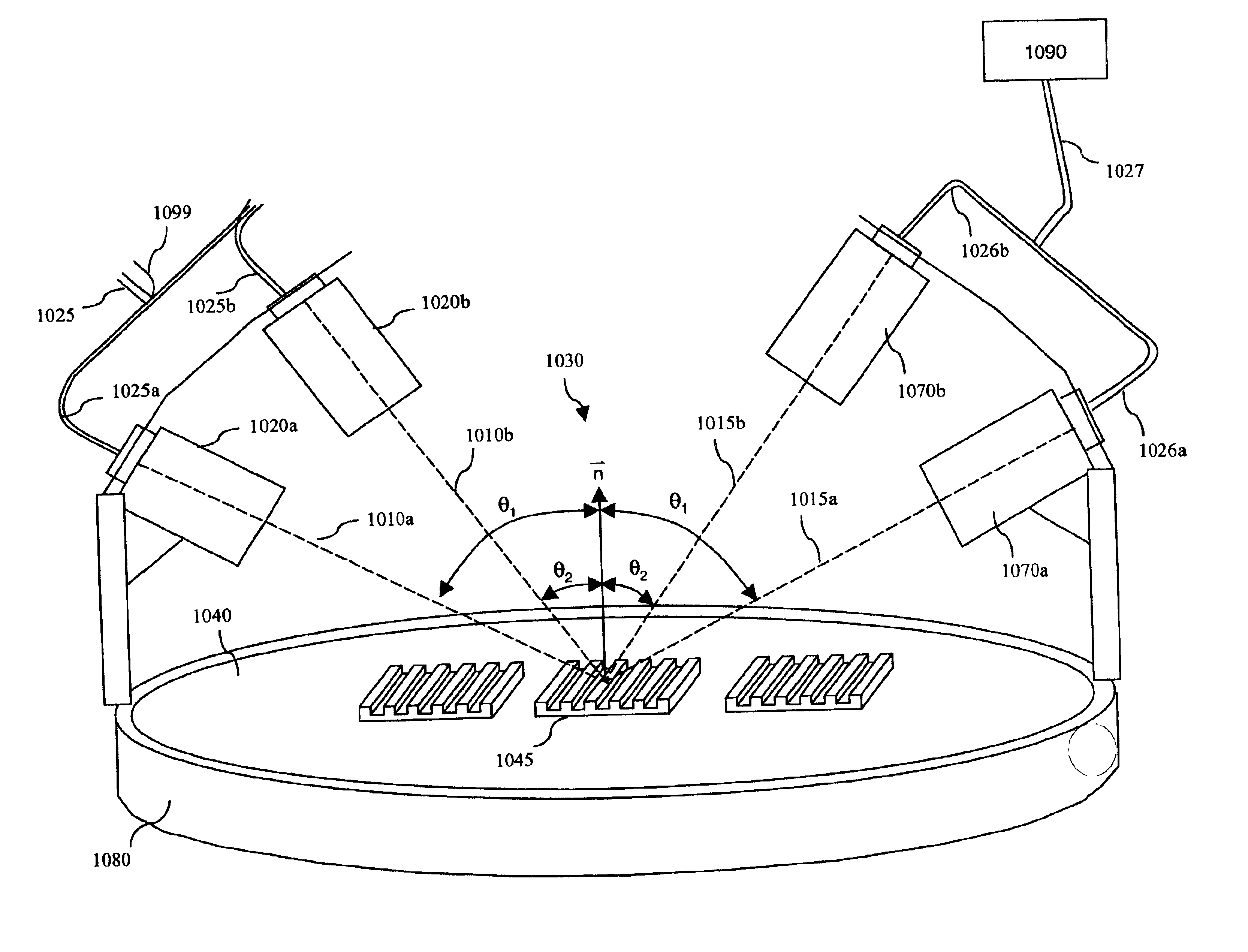
[0035]Section 1 of the present Detailed Description describes apparatus and methods for the acquisition of diffraction data from one-dimensionally and two-dimensionally repeating, regularly-spaced series of structures using optical metrology.

[0036]Section 2 of the present Detailed Description describes the mathematical formalism for RCWA calculations for the diffraction of TE-polarized incident radiation from a periodic grating. Definitions of the variables used in the present specification are provided, and intra-layer ...


PUM


Abstract

A library of simulated-diffraction signals for an integrated circuit periodic grating is generated by generating gets of intermediate layer data. Each set of intermediate layer data corresponding to a separate one of a plurality of hypothetical layers of a hypothetical profile of the periodic grating. Each separate hypothetical layer has one of a plurality of possible combinations of hypothetical values of properties for that hypothetical layer. The generated sets of intermediate layer data are stored. Simulated-diffraction signals for each of a plurality of hypothetical profiles are generated based on the stored generated sets of intermediate layer data.

Description

RELATED DOCUMENTS[0001]The present patent application claims the benefit of provisional patent application Ser. No. 60 / 178,910, filed Jan. 26, 2000, by Xinhui Niu and Nickhil Harshavardhan Jakatdar, entitled Cached Coupled Wave Method for Diffraction Grating Profile Analysis.BACKGROUND OF THE INVENTION[0002]The present invention relates generally to the measurement of complete profiles of one-dimensionally and two-dimensionally repeating, regularly-spaced series of structures through the use of an algorithm for caching of intermediate results, and the use of cached intermediate results to increase the efficiency of calculations. The present invention also relates to coupled wave analyses of diffracted electromagnetic signals from periodic gratings, particularly where the diffracted electromagnetic signals are monitored by optical metrology tools, such as reflectometer and ellipsometers. More particularly, the present invention relates to apparatus and methods for measurement of comp...

Claims


Application Information

Patent Timeline
Patent Type & Authority Patents(United States)
IPC IPC(8): G01B11/06G01B11/24G01B11/14G02B5/18
CPCG01B11/0675G02B5/18G01B11/2441G01B11/14G01B9/02
Inventor NIU, XINHUIJAKATDAR, NICKHIL HARSHAVARDHAN
Owner TOKYO ELECTRON US HOLDINGS INC
Learn More