Image display

a technology of image display and display screen, which is applied in the field of image display apparatus, can solve the problems of difficult selective determination, long time required, and difficult to search for a desirable diagnostic portion with respect to operators, and achieve the effect of high efficiency

Inactive Publication Date: 2005-05-10
HITACHI MEDICAL CORP
View PDF13 Cites 28 Cited by
  • Summary
  • Abstract
  • Description
  • Claims
  • Application Information

AI Technical Summary

Benefits of technology

[0020]As a consequence, a desirable diagnostic portion can be searched in a high efficiency from any one of the three sorts of images which are made of large amounts of data, and are acquired by employing the cone-beam reconstruction.
[0021]Also, in accordance with the present invention, only such three-sorts of the three-dimensional original images are saved and used as the normal display subjects, which are located between the two planes opposite to each other of the polyhedron which is internally contacted to the three-dimensional original images. As a result, the three-dimensional original images corresponding to the normal display subjects can be displayed in a short time period, while using a small amount of the saved images.

Problems solved by technology

However, in the conventional image display apparatus, since a very large number of axial images are obtained by way of the cone-beam reconstruction, there is such a problem that while this very large number of axial images, and both the sagittal images and the coronal images which are obtained from the axial images are displayed on the monitor, searching of a desirable diagnostic portion may constitute very hard works with respect to operators.
Thus, there is another problem that lengthy time is required so as to read out all of these axial images from the magnetic disk and to load the read axial images on the main memory.
However, this conceivable method requires the storage capacity of the magnetic disk which is three times larger than that of the above-explained method, resulting in a not-preferable method.
Also, when an image is displayed, it is not easy to selectively determine that which image among the above-explained three sorts of images is displayed.

Method used


Image

  • Image display
  • Image display
  • Image display

Examples


Embodiment Construction

[0038]Various preferable embodiment modes of an image display apparatus according to the present invention will now be described in detail with reference to the accompanying drawings.

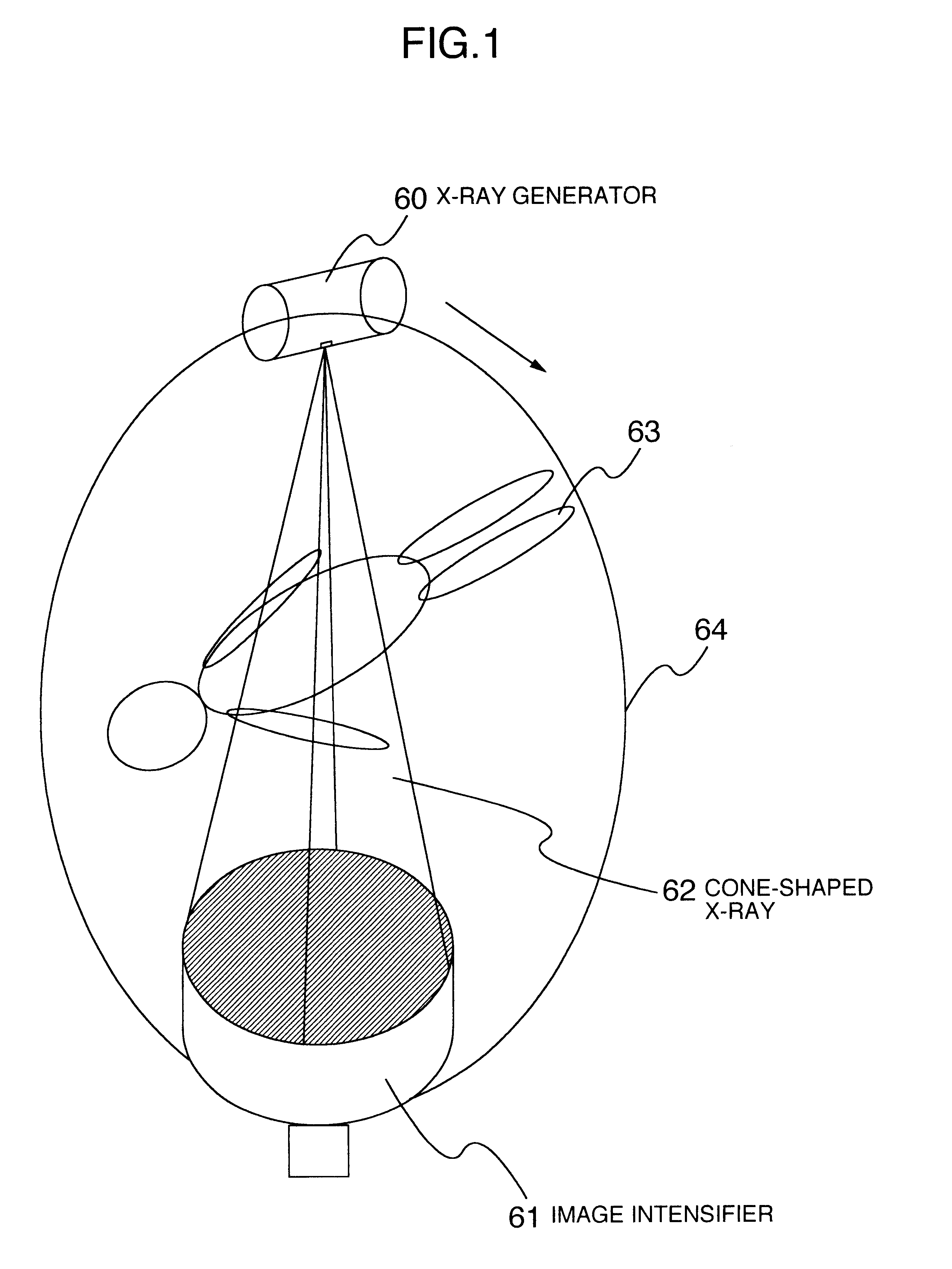
[0039]FIG. 1 is an explanatory diagram for indicating an arrangement of an X-ray CT apparatus to which an image processing apparatus of the present invention is applied. A cone-shaped X-ray 62 generated from an X-ray generator 60 penetrates, or passes through an object under examination 63, and a transmission X-ray is entered into a circular image intensifier 61 which is provided opposite to the X-ray generator 60 so as to detect an amount of the transmission X-ray. The detected transmission X-ray amount is converted into an electric signal to obtain projection data. A tomographic image is obtained by processing the projection data.

[0040]Both the X-ray generator 60 and the image intensifier 61 are rotated around an orbit 64 located around the object under examination 63. Since the X-ray generator 60 and...


PUM


Abstract

In an image display apparatus capable of storing therein a small amount of images and also capable of displaying two sorts, or more of images within a short time period, an axial image 1, a sagittal image 2, and a coronal image 3, which are loaded from a magnetic disk, are displayed on a CRT monitor 117. Image position indication FIGS. 4, 5, 6 are indicated above the respective tomographic images, and positions of the respective tomographic images are indicated on the respective image position indication FIGS. 4, 5, 6 by employing heavy lines 4a, 5a, 6a, and triangular symbols 4b, 5b, 6b. The positions of the tomographic images can be adjusted by dragging the respective triangular symbols 4b, 5b, 6b by using a mouse 118. Image position input FIGS. 7, 8, 9 are indicated under the respective tomographic images, and the positions of the respective displayed tomographic images are indicated on the image position input FIGS. 7, 8, 9 by way of drag bars 7a, 8a, 9a. Alternatively, the positions of the tomographic images may be adjusted by dragging the drag bars 7a, 8a, 9a by using the mouse 118.

Description

TECHNICAL FIELD[0001]The present invention is related to an image display apparatus capable of displaying thereon such an image by irradiating cone-shaped X-ray beams to an object under examination, and for acquiring transmission X-rays as projection data by way of a two-dimensional sensor along multiple directions so as to reconstruct tomographic images and the like (will be referred to as “cone-beam reconstruction” hereinafter). More specifically, the present invention is directed to such an image display apparatus capable of displaying thereon a tomographic image (sagittal image), another tomographic image (sagittal image), or another tomographic image (coronal image), which are cone-beam-reconstructed by a CT apparatus, the axial image being acquired along a vertical direction with respect to a body axis of an object under examination, the sagittal image being acquired along a parallel direction with respect to the body axis of the object under examination and also along a direc...

Claims


Application Information

Patent Timeline
Patent Type & Authority Patents(United States)
IPC IPC(8): G06T11/80A61B6/03G06T1/00G06T11/00G06T15/00G06T15/08G16H10/60
CPCA61B6/032A61B6/4085G06T15/08A61B6/466A61B6/5223A61B6/463
Inventor GOTO, YOSHIHIROTAKAGI, HIROSHISHINOHARA, DAI
Owner HITACHI MEDICAL CORP
Why Eureka
Try Eureka