Air baffle for paper travel path within an electrophotographic machine

a technology of electrophotography and paper travel path, which is applied in the direction of electrographic process apparatus, instruments, optics, etc., can solve the problems of smearing of unfused images on sheets, and achieve the effect of effectively closing the gap and deflecting, reducing the possibility of sheets being smeared, and less drag forces

Active Publication Date: 2005-05-10
HEIDELBERG DIGITAL +1
View PDF7 Cites 10 Cited by
  • Summary
  • Abstract
  • Description
  • Claims
  • Application Information

AI Technical Summary

Benefits of technology

[0015]A deflector means (e.g. baffle) is positioned within this gap to effectively close the gap and deflect the air currents, which inherently flow into the gap during the copying operation, away from the sheet as the sheet moves from the vacuum transport onto the surface of the fuser guide. Thus, the deflector means prevents the force of these unwanted air currents from counteracting the vacuum forces on the sheet as it moves across the surface of the guide and into the fuser section. That is, if unabated, these air currents would act directly against the sheet and tend to push the sheet off of the guide surface as the sheet moved across the gap. If the vacuum being applied by the guide is not strong enough, the force of the air current could cause the sheet to sag downward off the guide's surface thereby resulting in possible smearing of the unfused image on the sheet.
[0016]Also, by shielding the gap from these unwanted air currents, the vacuum transport fans (i.e. air movers) present in the apparatus will now evacuate air from the substantially closed gap thereby creating a substantial static pressure drop (i.e. vacuum) in the gap area. This vacuum, now inherently present in the gap, will act to hold the sheet upward as it moves across the gap and onto the guide's surface thereby alleviating the possibility that a portion of the sheet (i.e. trail end) may sag as it moves across the gap.
[0017]Accordingly, by blocking the unwanted air currents and inherently producing a vacuum within the gap, the present invention allows a smaller vacuum to be used for holding the sheet against the fuser guide and into the fuser section. By using a smaller vacuum, there are less drag forces on the moving sheet thereby reducing the possibility that the sheet may stall on the guide. Also, the smaller vacuum requires smaller air movers, which, in turn, reduces the overall cost of the apparatus.

Problems solved by technology

If the vacuum being applied by the guide is not strong enough, the force of the air current could cause the sheet to sag downward off the guide's surface thereby resulting in possible smearing of the unfused image on the sheet.

Method used


Image

  • Air baffle for paper travel path within an electrophotographic machine
  • Air baffle for paper travel path within an electrophotographic machine
  • Air baffle for paper travel path within an electrophotographic machine

Examples


Embodiment Construction

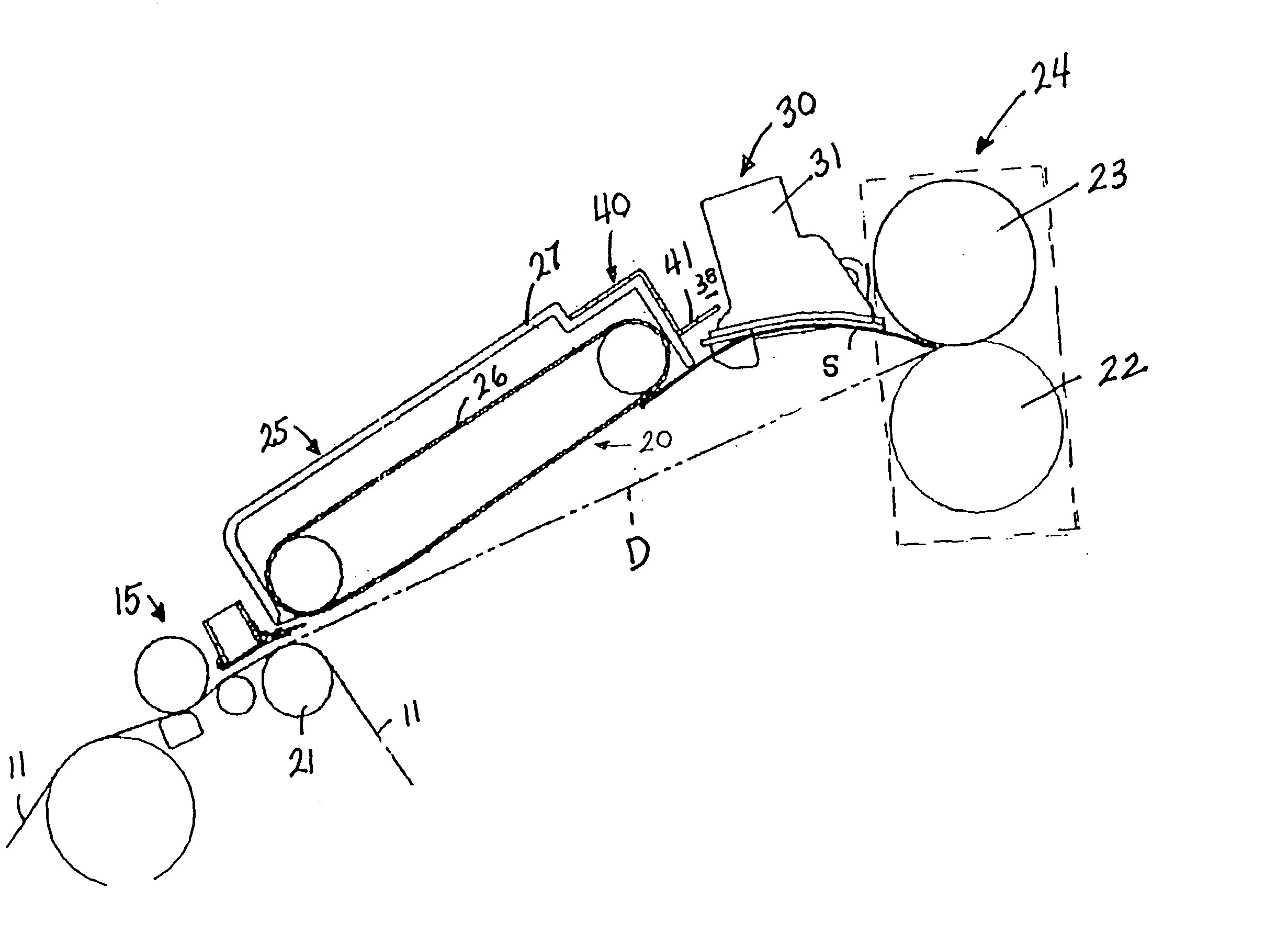
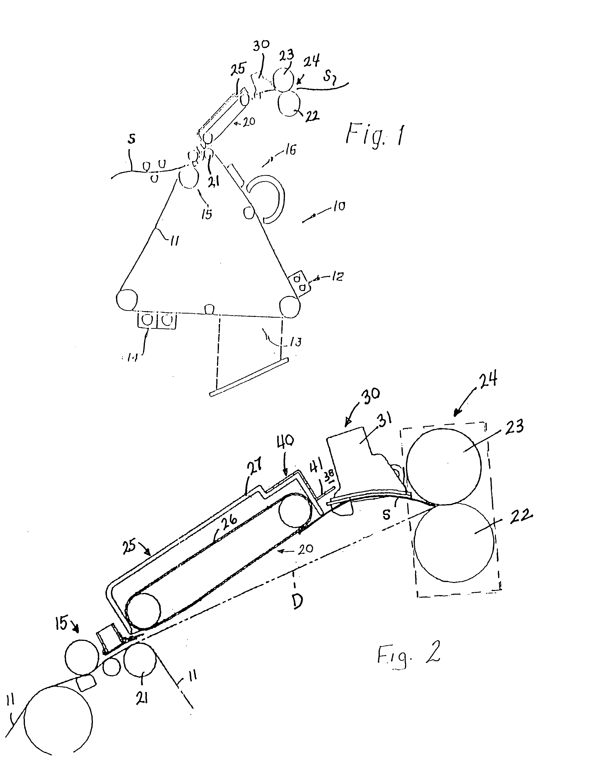
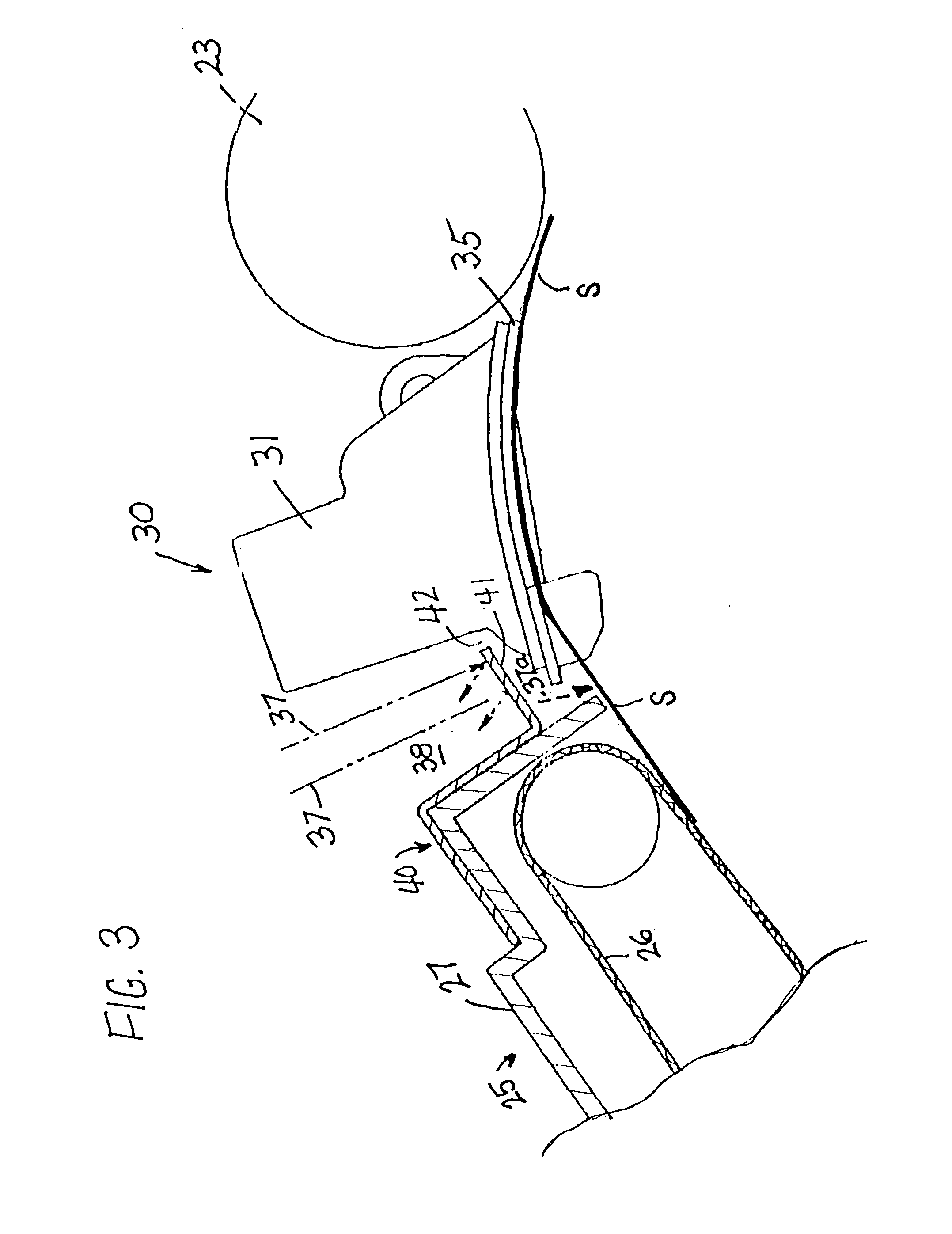
[0025]FIG. 1 illustrates a typical electrophotographic apparatus or machine 10 (e.g. copier, duplicator, printer) in which the present invention can be incorporated. Machine 10 is of the type that uses an endless photoconductor member 11 (e.g. photographic film) to transfer a copy of an inputted image onto a sheet S of a copy medium. The film moves through a closed loop past a charging section 12, an exposure or input section 13, a developing section 14, an image transfer section 15, and an erase / clean section 16. Sheet S of a copy medium (e.g. paper) is fed from a supply (not shown) through image transfer section 15 where the toner image on the film 11 is transferred to the sheet S. Sheet S is then fed along a travel path 20 from a detack roller 21 in the image transfer section 15 to a fuser section 24 where the sheet S passes through the “nip” between a fusing roller 22 and a pressure roller 23 to thereby “fuse” the toner image onto sheet S before the sheet exits the machine.

[002...


PUM


Abstract

A means and a method for increasing the efficiency of a vacuum-assisted, fuser entrance guide in an electrophotographic apparatus by blocking and deflecting air currents away the sheet of copy medium as the sheet moves from a vacuum transport towards the entrance guide. A baffle is positioned in the gap between the vacuum transport and the fuser entrance guide that form the travel path for the sheet through the apparatus. The baffle has a deflecting surface that extends substantially across the gap, which diverts the air currents away from the sheet.

Description

[0001]This application claims the benefit of Provisional Application No. 60 / 413,396, filed Sep. 25, 2002.FIELD OF THE INVENTION[0002]The present invention relates to the paper travel path within an electrophotographic copier / printer apparatus and in one of its aspects relates to an air baffle for diverting air away from a sheet of paper as the paper moves along a travel path between an image transfer loop (film) and the entrance of the fuser section of an electrophotographic apparatus.BACKGROUND OF THE INVENTION[0003]In a typical electrophotographic machine (e.g. copier, duplicator, printer, etc.), a continuous loop of a photoconductor film is commonly used to transfer an image from an input section onto a copy medium (e.g. a sheet of paper or the like). The film is initially charged and passed through an input section where an image is projected onto the charged film. The film then moves through a developing section where toner is applied to the charged image, and on through an ima...

Claims


Application Information

Patent Timeline
Patent Type & Authority Patents(United States)
IPC IPC(8): G03G15/00
CPCG03G15/657
Inventor GIANNETTI, JOHNCAIAZZA, GIOVANNI B.SLEVE, JEROME F.
Owner HEIDELBERG DIGITAL
Why Eureka
Try Eureka