Polyhedron inspection feeder and polyhedron inspection apparatus

a technology of polyhedrons and inspection feeders, applied in the direction of instruments, using mechanical means, transportation and packaging, etc., can solve the problems of high labor intensity, high labor intensity, and inability to meet the needs of workers, and achieve the effect of miniaturizing the device structure and high accuracy

Inactive Publication Date: 2005-05-17
LINTEC CORP
View PDF20 Cites 3 Cited by
  • Summary
  • Abstract
  • Description
  • Claims
  • Application Information

AI Technical Summary

Benefits of technology

[0006]The present invention has been proposed in view of the problems. Accordingly, an object of the present invention is to provide a polyhedron inspection feeder and a polyhedron inspection apparatus, which can automatically and effectively inspect a surface of chip-like inspection object with high accuracy, and can miniaturize the device structure.

Problems solved by technology

However, in the above-mentioned inspection, the worker takes these chips by his hand one by one, and then, visibly inspects them; for this reason, there are many cases where defects such as micro scratch and deformation have been overlooked.
As a result, this is a factor of mixing defectives in products.
Further, the worker is fatigued with the inspection; for this reason, he has a heavy workload.
In addition, a problem arises such that great unevenness is caused in inspection accuracy depending upon worker's skill.
However, the above apparatus requires a mechanism for reversing the inspection object between the first and second conveyers; for this reason, a problem arises such that the structure becomes complicate.
Further, in order to reverse the inspection object, the first and second conveyers can not be linearly arranged; for this reason, a predetermined space is required in a vertical direction as conveyer arrangement space, whereby a problem arises such that the apparatus is made into a large size.

Method used


Image

  • Polyhedron inspection feeder and polyhedron inspection apparatus
  • Polyhedron inspection feeder and polyhedron inspection apparatus
  • Polyhedron inspection feeder and polyhedron inspection apparatus

Examples


Embodiment Construction

[0025]One embodiment of the present invention will be described below with reference to the accompanying drawings.

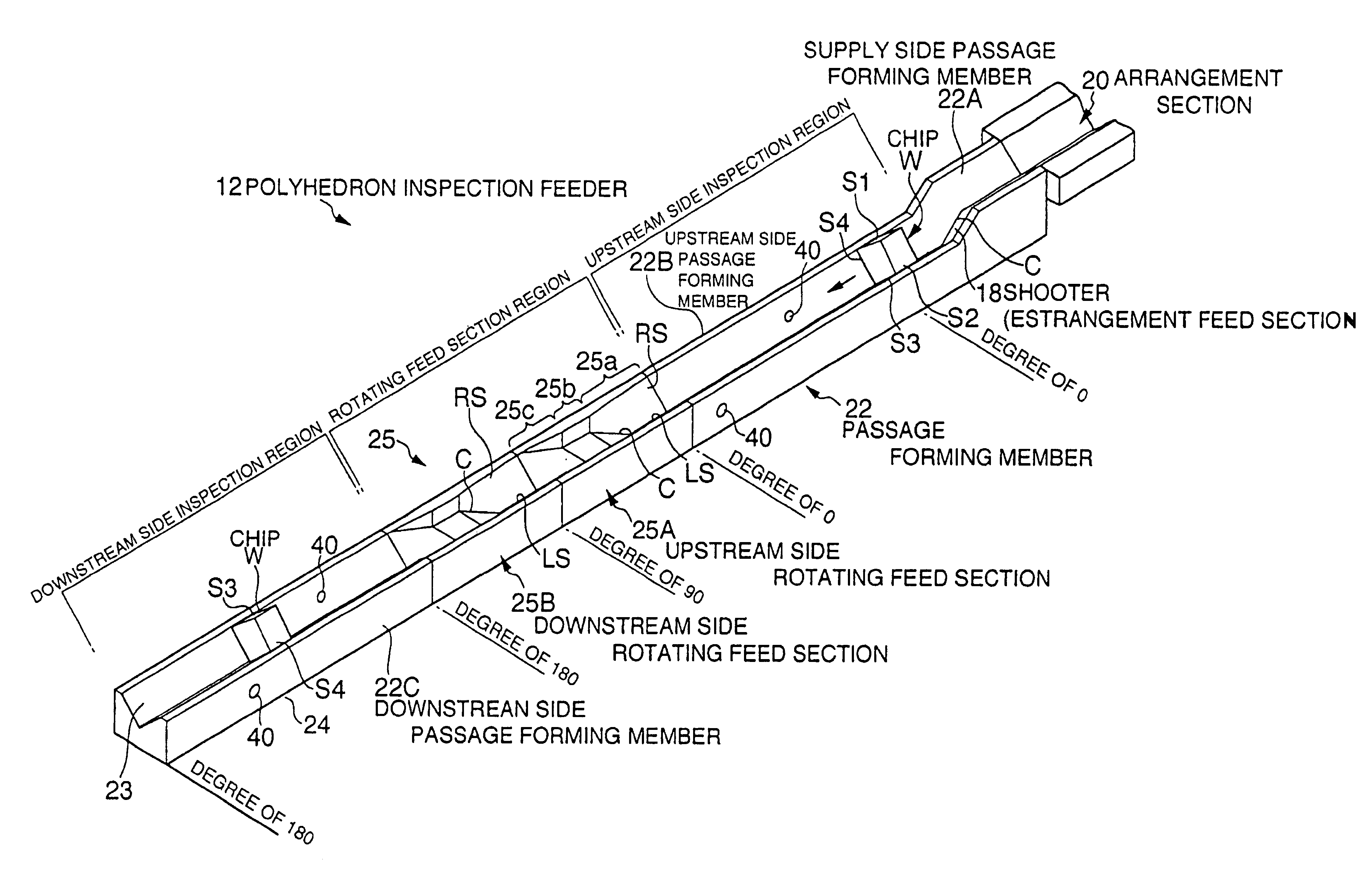
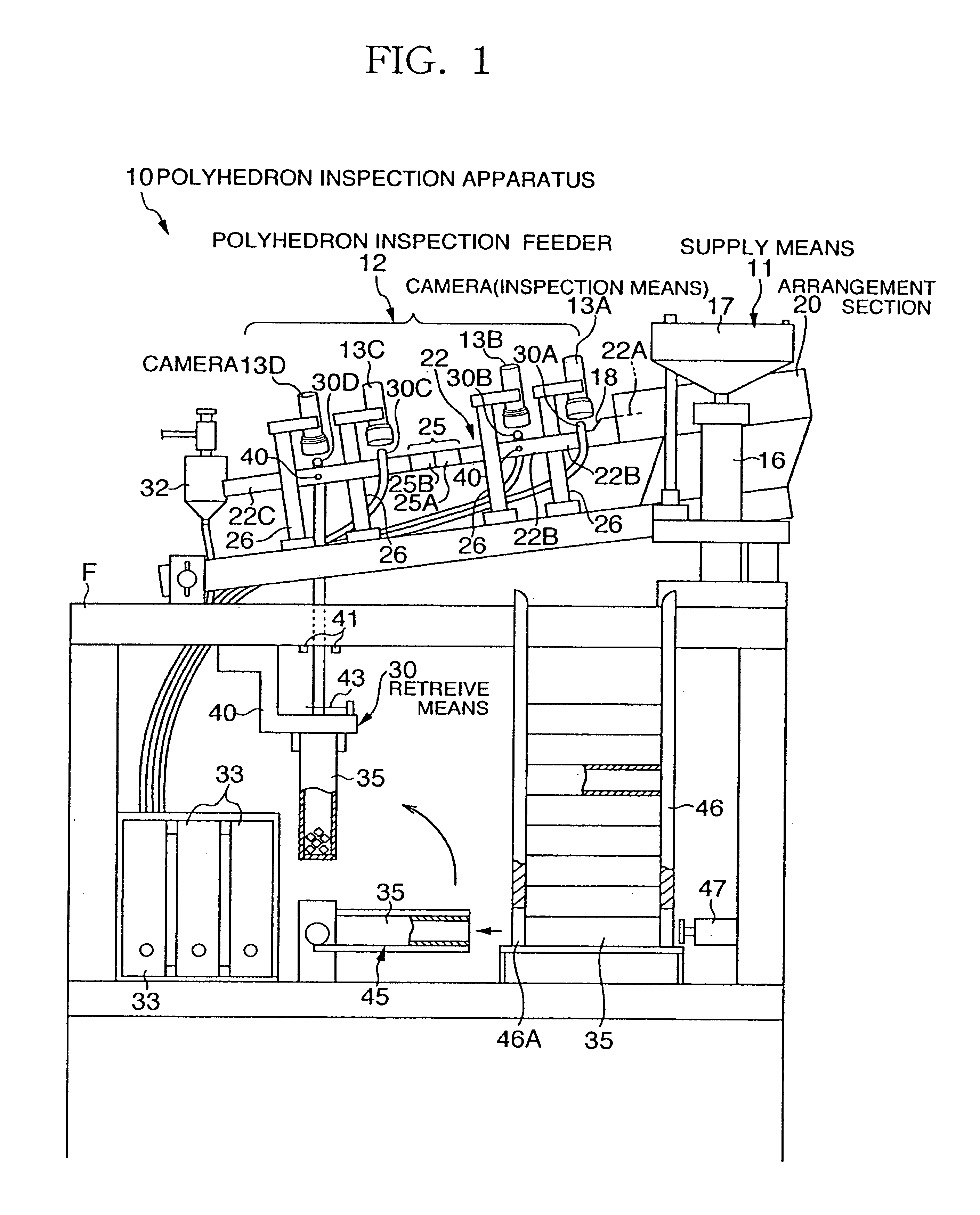
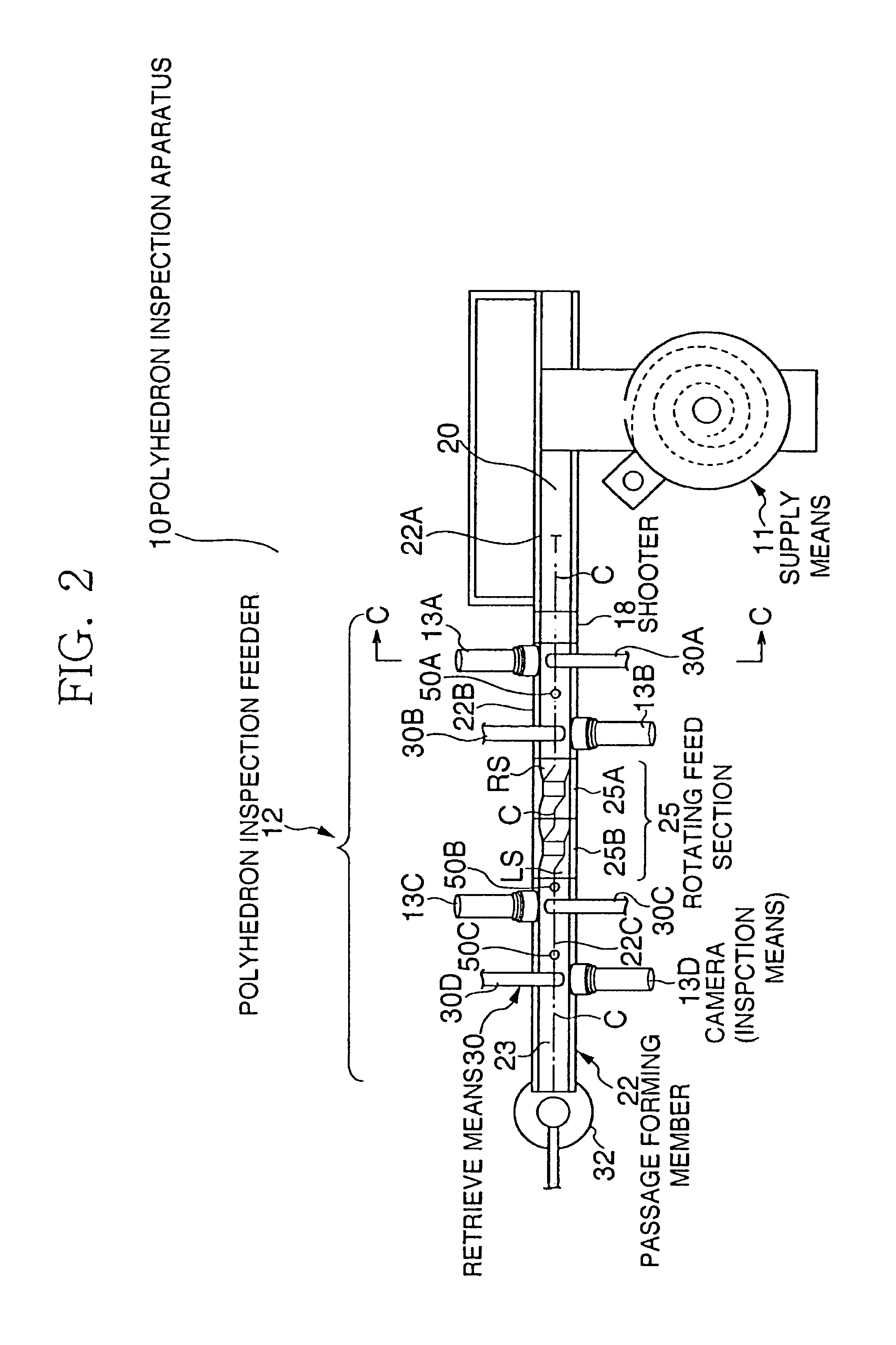
[0026]FIG. 1 is a front view schematically showing the whole configuration of polyhedron inspection apparatus to which the present invention is applied, and FIG. 2 is a top plan view showing principal parts of the polyhedron inspection apparatus shown in FIG. 1. As shown in FIG. 1 and FIG. 2, the polyhedron inspection apparatus 10 includes a supply means 11, a polyhedron inspection feeder 12 (see FIG. 2), first to fourth cameras 13A to 13D used as inspection means, and a retrieve means 30. More specifically, the supply means 11 is arranged on an upper portion of a frame F, and the polyhedron inspection feeder 12 moves an inspection object supplied from the supply means 11, that is, a cube-like ceramic chip capacitor (hereinafter, referred to as chip W) in this embodiment. The first to fourth cameras 13A to 13D are arranged above the polyhedron inspection feeder 12, and t...


PUM

PropertyMeasurementUnit
angleaaaaaaaaaa
angleaaaaaaaaaa
angleaaaaaaaaaa

Abstract

A polyhedron inspection apparatus 10 includes a polyhedron inspection feeder 12 having a passage forming member 22 for inspecting a surface of cubic chip W. The polyhedron inspection feeder 12 is formed with a V-letter groove, and includes two rotating feed sections 25A and 25B arranged on the midway of the passage forming member 22. The rotating feed sections 25A and 25B are individually formed with grooves having V-letter type, U-letter type and V-letter type sectional shapes in succession. The passage forming member 22 is provided with a shooter 18 for moving the chip W one by one in a state of being estranged from each other, and further, is provided with cameras 13A to 13D for inspecting the surface of the chip W, and retrieve element 30 for retrieving the chip W in accordance with the inspection result.

Description

RELATED APPLICATIONS[0001]This application is a divisional of U.S. patent application Ser. No. 10 / 181,374, filed Oct. 7, 2002, which is the National Stage of International Application No. PCT / JP01 / 11514 Dec. 27, 2001, Which claims priority of Japanese Application Nos. 2000-404981 and 2001-127248.TECHNICAL FIELD[0002]The present invention relates to a polyhedron inspection feeder and a polyhedron inspection apparatus, and in particular, to a polyhedron inspection feeder and a polyhedron inspection apparatus, which are suitable for inspecting a surface accuracy of inspection object such as chips of electronic components.BACKGROUND ART[0003]Conventionally, in the case of inspecting finish surface accuracy of electronic components such as chips, each surface of these chips has been inspected by a worker using a loupe or the like. However, in the above-mentioned inspection, the worker takes these chips by his hand one by one, and then, visibly inspects them; for this reason, there are ma...

Claims


Application Information

Patent Timeline
Patent Type & Authority Patents(United States)
IPC IPC(8): B07C5/342B07C5/02B07C5/00H01L21/00G01N21/89B65G47/22
CPCB07C5/02B07C5/342H01L21/67271G01B11/24
Inventor KIMURA, TAKASHIKIKAWA, KAZUHIRO
Owner LINTEC CORP
Why Eureka
Try Eureka