Wheel structure

a technology of wheel structure and electric motor, which is applied in the direction of electric propulsion mounting, braking system, cycles, etc., can solve the problems of affecting the performance of the brake mechanism, degrading the performance of the electric motor, and not being suitable for a motorcycle, so as to prevent the electric motor from being used, the effect of improving the wheel structur

Inactive Publication Date: 2005-05-17
HONDA MOTOR CO LTD
View PDF13 Cites 15 Cited by
  • Summary
  • Abstract
  • Description
  • Claims
  • Application Information

AI Technical Summary

Benefits of technology

[0009]An object of the present invention, therefore, is to improve the wheel structure, and to prevent the electric motor from being adversely influenced by wear powders of the brake mechanism.
[0010]Another object of the present invention is to prevent the brake mechanism from being adversely influenced by heat generated by the electric motor and, at the same time, to provide a small, compact wheel having a built-in electric motor.

Problems solved by technology

Consequently, the structure is not suitable for a motorcycle, for example.
Moreover, mechanism wear powders may adhere to the field 8 in the wheel, degrading the performance of the electric motor.
In addition, heat generated by the electric motor may degrade the performance of the brake mechanism.

Method used


Image

  • Wheel structure
  • Wheel structure
  • Wheel structure

Examples


Embodiment Construction

[0031]An embodiment of the invention will be described hereinbelow with reference to the attached drawings.

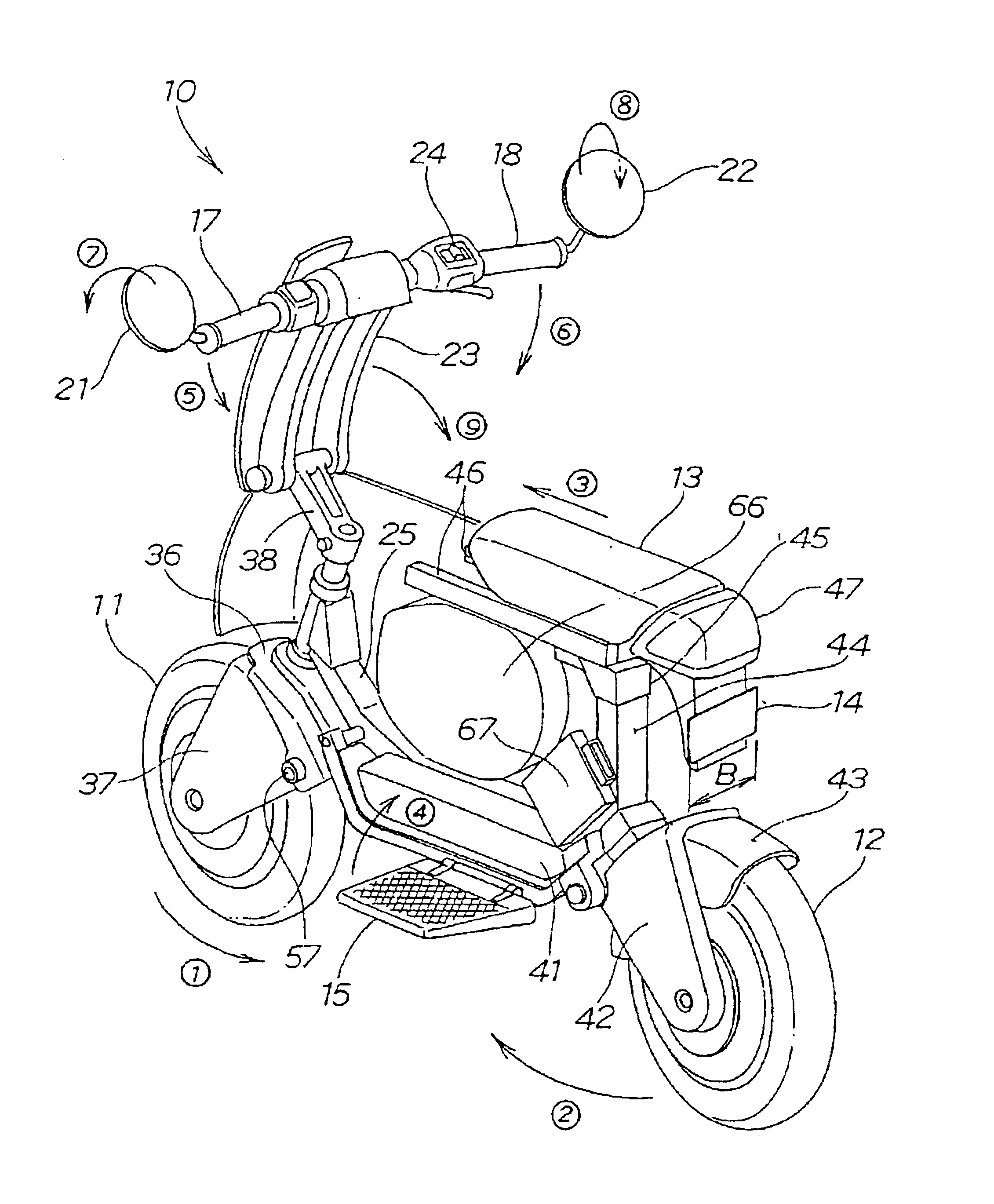
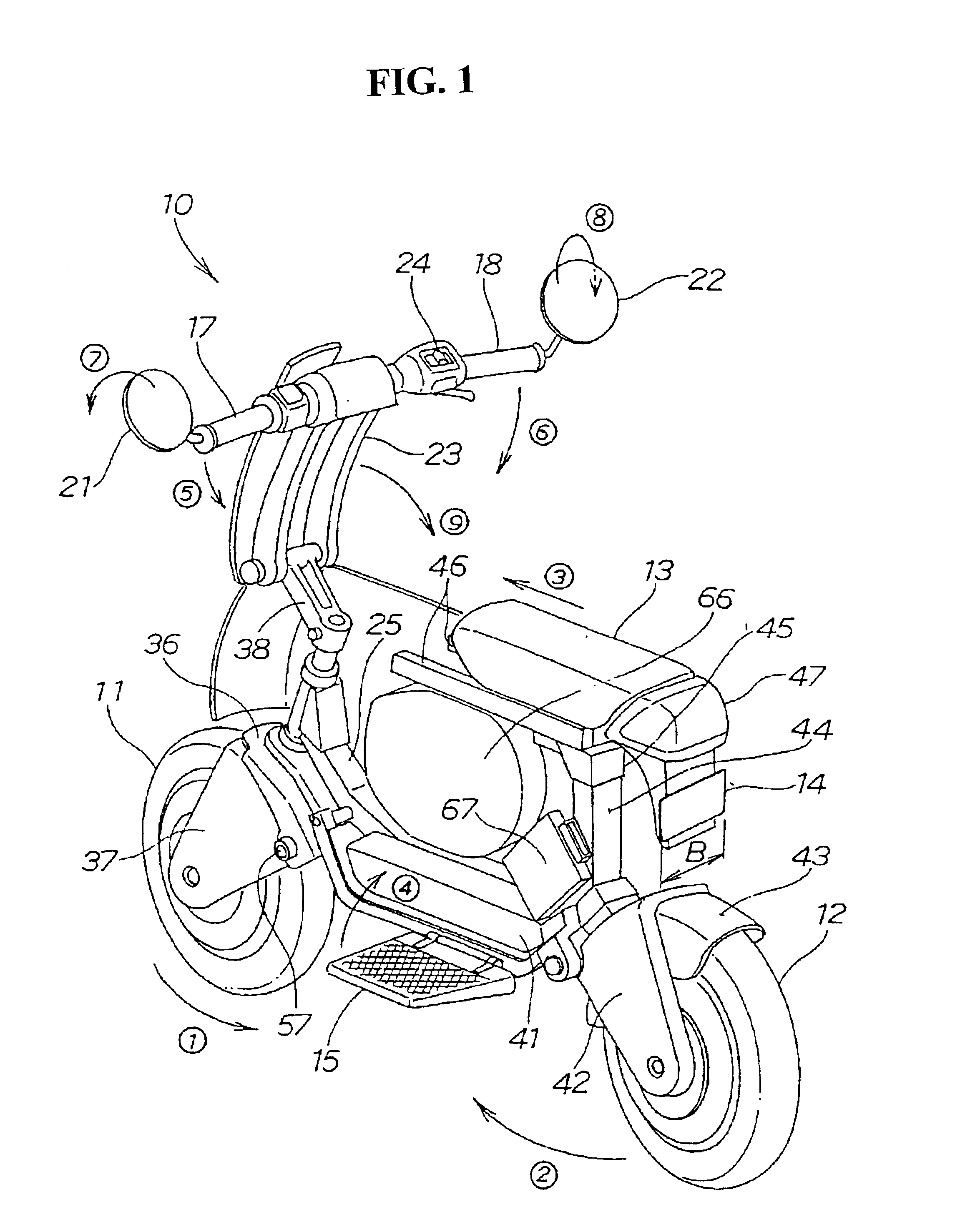
[0032]FIG. 1 is a perspective view of a foldable two-wheel vehicle employing a wheel structure according to the invention. A foldable two-wheel vehicle 10 is a has an outside dimension that can be reduced by folding a part of the vehicle, so that it can be mounted on and carried by a larger four-wheel vehicle.

[0033]In the two-wheel vehicle 10, a front wheel 11 and a rear wheel 12 can be moved, or folded, in the directions of the arrows {circle around (1)} and {circle around (2)}. A seat 13 moves forward in the direction of the arrow 3. Projected portions, such as steps 15 and 16 (step 16 on the depth side is not shown) on which the driver puts his / her feet, handlebars 17 and 18, and rear-view mirrors 21 and 22 are folded in the directions of the arrows {circle around (4)} to {circle around (8)}, respectively, so as to be within the width B of a license plate 14 attached to the ...


PUM


Abstract

A drum brake for braking a wheel disposed on the inside in the radial direction of an electric motor. The drum of the drum brake and an electric motor are disposed separate from each other, and thus wear powders of a brake shoe do not adhere to a permanent magnet of the electric motor. As a result, the wear powders do not adversely influence the performance of the electric motor, and the performance of the electric motor is maintained. The electric motor and the drum brake are disposed concentrically, so that the width of the wheel is reduced. Thus, a small and compact wheel is realized.

Description

CROSS-REFERENCE TO RELATED APPLICATION[0001]The present application claims priority under 35 U.S.C. §119 to Japanese Patent Application No. 2001-271640, filed Sep. 7, 2001, the entire contents of which are hereby incorporated by reference.BACKGROUND OF THE INVENTION[0002]1. Field of the Invention[0003]The present invention relates to an electric motor built-in wheel structure, in which an electric motor is not influenced by wear powders of a brake mechanism and the brake mechanism is not influenced by beat of the electric motor, and which is small and compact.[0004]2. Description of Background Art[0005]One example of a conventional wheel structure for a vehicle is shown in Japanese Unexamined Utility Model No. Sho-49-132546, entitled “Electrically operated small vehicle”.[0006]FIG. 2 of the publication describes a wheel structure with a hub 5 rotatably attached to an axle 6 via a bearing 7, a tire 4 attached to the hub 5, and an electric motor disposed in a wheel by attaching an arm...

Claims


Application Information

Patent Timeline
Patent Type & Authority Patents(United States)
IPC IPC(8): B60T1/00B60T11/04B60T1/06B60T11/00B62M7/12B62M7/00F16D65/02F16D65/10F16D51/00H02K7/14B60K7/00B60B37/00B62M6/65F16D51/22F16D65/00
CPCB60T1/067B60T11/04B62M7/12F16D51/20F16D65/10H02K7/14F16D51/00B60K7/0007B62K2204/00F16D2065/138
Inventor MAKUTA, YOHEITAKAYANAGI, SHINJISAKAMOTO, TOMOKAZU
Owner HONDA MOTOR CO LTD
Why Eureka
Try Eureka