Bumper structure

a bumper and face technology, applied in the direction of bumpers, roofs, pedestrian/occupant safety arrangements, etc., can solve the problems of increasing the number of components, complicated structure, and difficulty in forming such an impact absorption member integrally with the lower portion of the bumper face, so as to achieve the effect of simple structure and increase the number of components

Inactive Publication Date: 2005-05-17
SUBARU CORP
View PDF8 Cites 45 Cited by
  • Summary
  • Abstract
  • Description
  • Claims
  • Application Information

AI Technical Summary

Benefits of technology

[0006]The present invention was made in these situations, and an object of the present invention is to provide a bumper structure in which a lower portion of a bumper face can fasten to a cross member. The object of the present invention is also to provide an appropriate impact absorbing function at the lower portion of the bumper face with a simple structure and without increasing the number of components.

Problems solved by technology

However, interposing the bracket between the bumper face and the cross member, as described above, causes an increase in the number of components and results in a complicated structure.
However, it is difficult to form such an impact absorbing member integrally with the lower portion of the bumper face.
Even if it were possible to form the impact absorbing member integrally with the lower portion of the bumper face, it would be difficult to tune the strength of the lower portion of the bumper in such a bumper structure.

Method used


Image

  • Bumper structure
  • Bumper structure
  • Bumper structure

Examples


Embodiment Construction

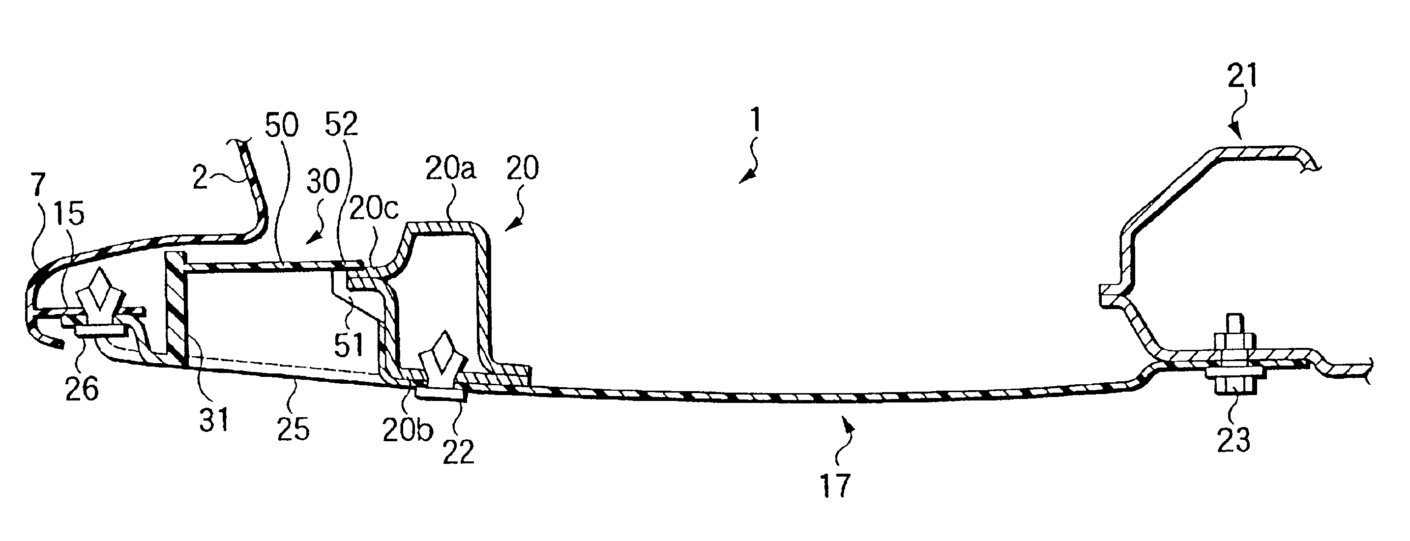
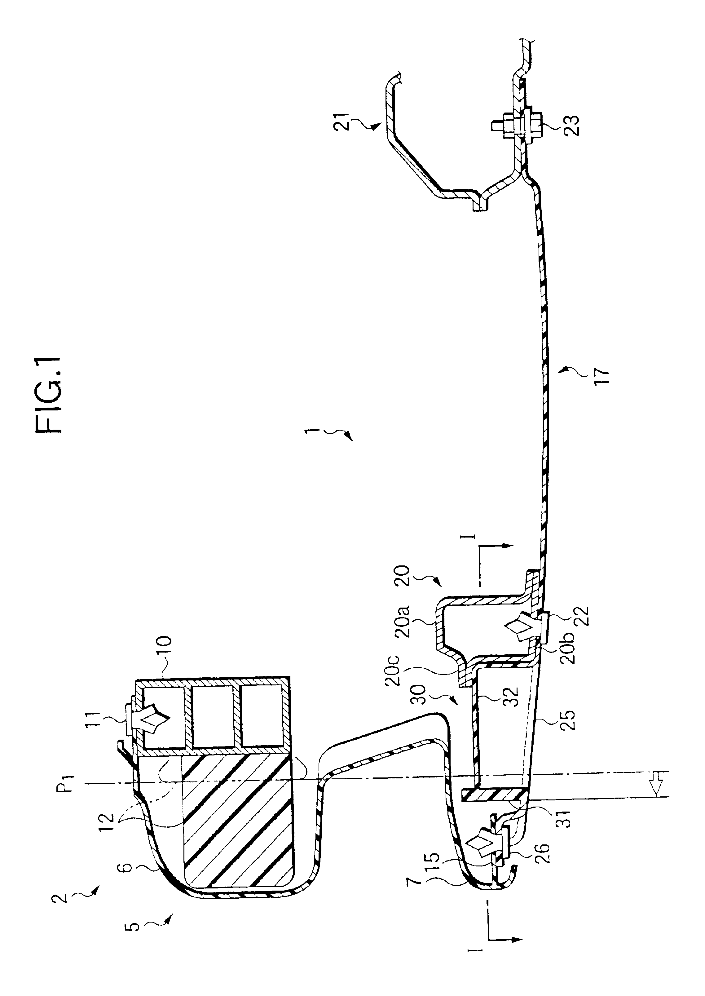
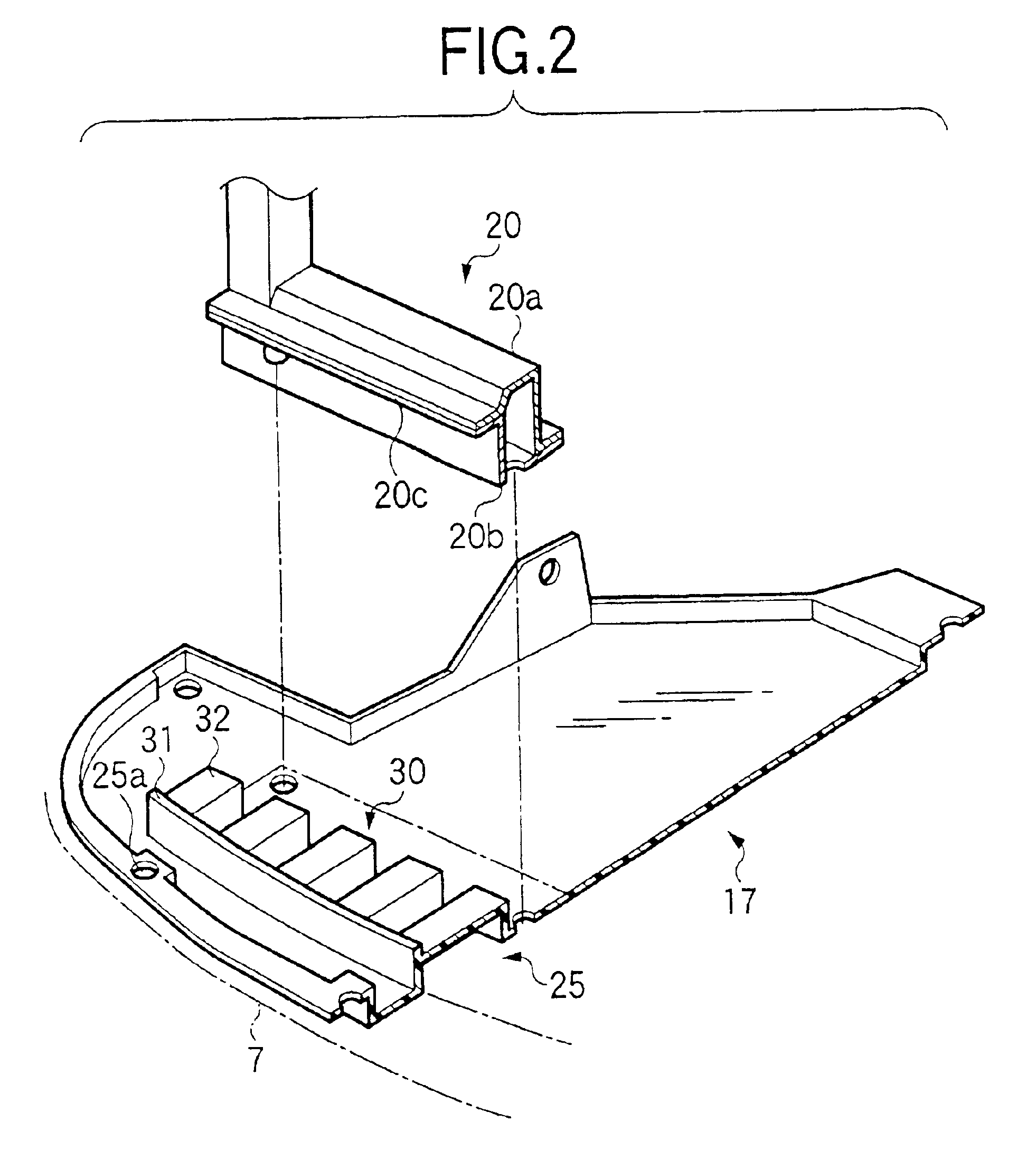
[0022]Referring to the appended drawings, a mode for carrying out the present invention will be described below. FIGS. 1 to 4 show a first embodiment of the present invention. FIG. 1 is a longitudinally vertical sectional view showing a main part of a vehicle body in the vicinity of a front bumper. FIG. 2 is an exploded perspective view of a cross member and an under cover. FIG. 3 is a plan view showing the main part of the under cover which corresponds to a horizontal sectional view taken along the line I—I in FIG. 1. FIG. 4 is longitudinally vertical sectional view showing a main part of a lower portion of the bumper.

[0023]In FIG. 1, reference numeral 1 denotes a vehicle body and reference numeral 2 denotes a front bumper disposed at a front end of the body 1.

[0024]The front bumper 2 has a bumper face 5 made from resin. The bumper face 5 has an upper protruding portion 6 and a lower protruding portion 7, which protrude at positions spaced a predetermined interval each other in a v...


PUM


Abstract

A front portion of an under cover fastened to a cross member extends to the front, so that the extension is formed as a mounting bracket for a bumper face. A lower impact absorbing member is integrally formed on the bracket which lower impact absorbing member has a rib provided to erect from the bracket in such a manner as to be opposed to an inner vertical surface of a lower protruding portion of the bumper face and a plurality of beads disposed behind the rib for transmitting an impact from the rib to the cross member, to thereby provide a bumper structure with appropriate impact absorbing function at a lower portion thereof, with a simple structure and without increasing the number of components.

Description

BACKGROUND OF THE INVENTION[0001]The present invention relates to a bumper structure in which an impact can be absorbed even at a lower portion of a bumper.[0002]In recent years, there have been proposed front bumpers for vehicle bodies in each of which protection of a pedestrian is taken into consideration. The front bumpers are formed in such a manner that an impact can be absorbed at a lower portion of the bumper as well as at an upper portion thereof.[0003]In a bumper structure like this, for example, in Japanese Patent Laid-open-2000-6739, it is disclosed a technology in which a bracket is interposed between a bumper face and a cross member so that it fastens a lower portion of the bumper face to the cross member on a vehicle body. The bracket has a plurality of mounting surfaces to overlap a front surface of the cross member. The bracket has pairs of vertical surfaces extending forward from both sides of the respective mounting surfaces in a direction substantially normal to a...

Claims


Application Information

Patent Timeline
Patent Type & Authority Patents(United States)
IPC IPC(8): B60R21/34B60R19/18B60R19/56B60R19/00B62D25/20B60R19/12B60R19/16B60R19/24B60R19/48
CPCB60R19/18B60R21/34B60R2019/1873B60R19/56
Inventor SATOU, KENICHI
Owner SUBARU CORP
Why Eureka
Try Eureka