Connector assembly for electrical interconnection

a technology of connecting parts and connectors, which is applied in the direction of coupling contact members, coupling device connections, electric discharge lamps, etc., can solve the problems of electrical disconnection, electrical disconnection, electrical disconnection of connecting members, etc., and achieves the effect of reducing stress or strain on the connecting members and the connector assembly

Inactive Publication Date: 2005-05-17
VISTEON GLOBAL TECH INC
View PDF16 Cites 61 Cited by
  • Summary
  • Abstract
  • Description
  • Claims
  • Application Information

AI Technical Summary

Benefits of technology

[0004]It is one aspect of the present invention to provide an improved connector assembly for electronic interconnection. The connector assembly includes an increased contact surface area between connecting members. As a result, stress on the connecting members and on the connector assembly is lessened, since force or resistance is distributed to a proportionally larger surface area. The connector assembly of the present invention includes and a printed circuit board (PCB) to which a male insert connects. The male insert has a strain relief tail connected to the printed circuit board and extends to a contact head. The strain relief tail is configured to be compressed during operation of the connector assembly to relieve stress or strain from the male insert and, in turn, the connector assembly. The contact head is cylindrically shaped, in one embodiment, and provides an increased amount of surface area per contact force to allow contact force to be distributed more uniformly.
[0005]The connector assembly further includes a female socket having receiving members biasingly spaced apart from each other to define an opening through which the male insert is disposed. When the male insert is disposed within the receiving members, the female socket is radially engaged with the contact head of the male insert. This allows the contact force to be distributed more uniformly about the contact head and provides an improved retention force which lessens a likelihood of disengagement resistance. The connector assembly further includes a connector housing to which the female socket is mounted. The connector assembly further has a connecting member which is configured to cooperate with the connector housing to secure the male insert with the female socket, defining a locking mechanism. This locking mechanism further provides an increased retention force between the male insert and the female socket.

Problems solved by technology

For example, manufacturers of electrical connectors have been challenged in producing electrical connectors and joints which have lower electrical resistance and higher retention force.
Some electrical connectors have a substantial amount of continuity resistance which lead to electrical disengagement.
In some situations, electrical disengagement of connecting members may be due to high stress or pressure on the connector.
Manufacturers have also been challenged in designing electrical connectors which are able to absorb pressure or distribute force placed thereon.

Method used


Image

  • Connector assembly for electrical interconnection
  • Connector assembly for electrical interconnection
  • Connector assembly for electrical interconnection

Examples


Embodiment Construction

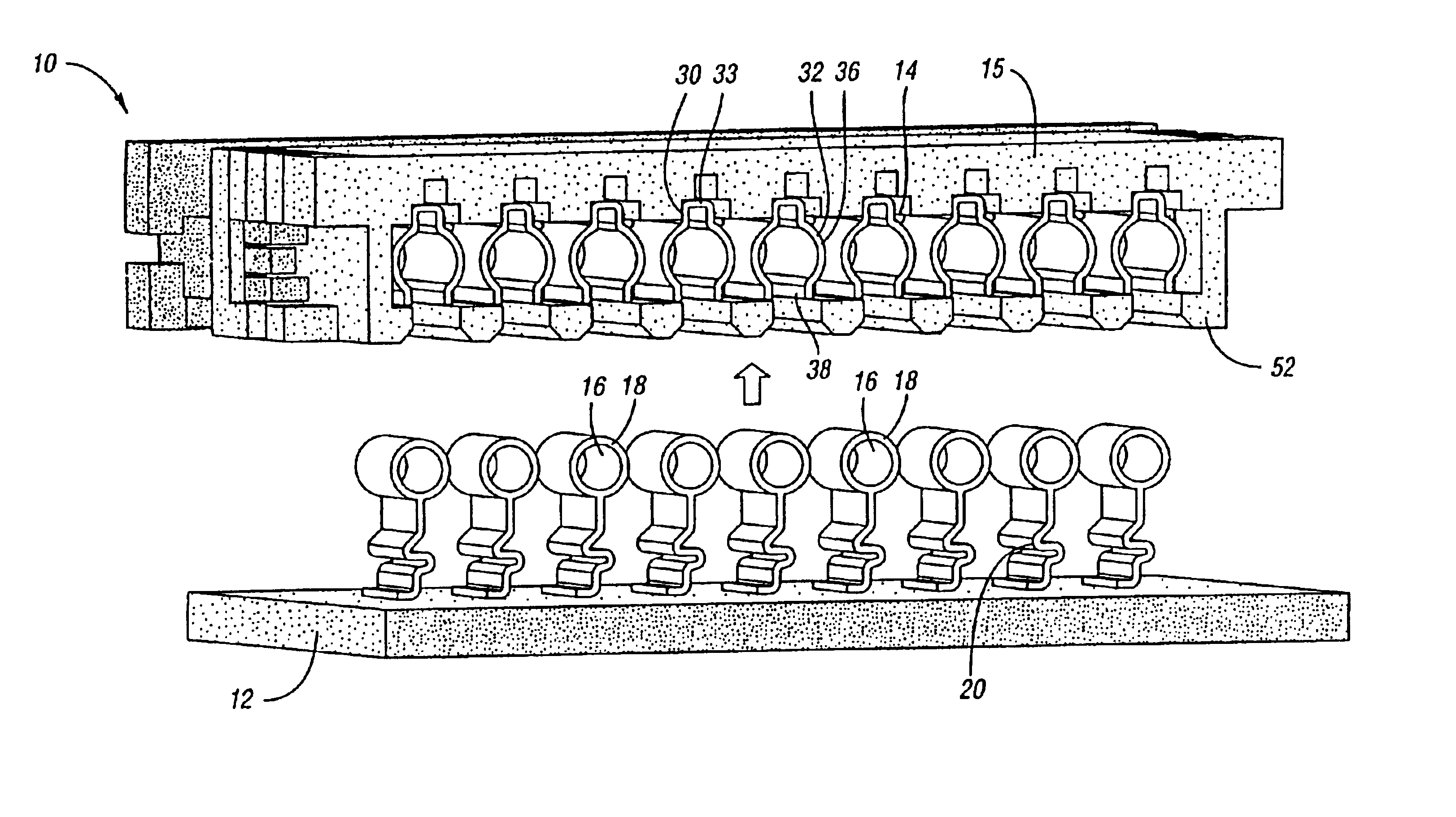
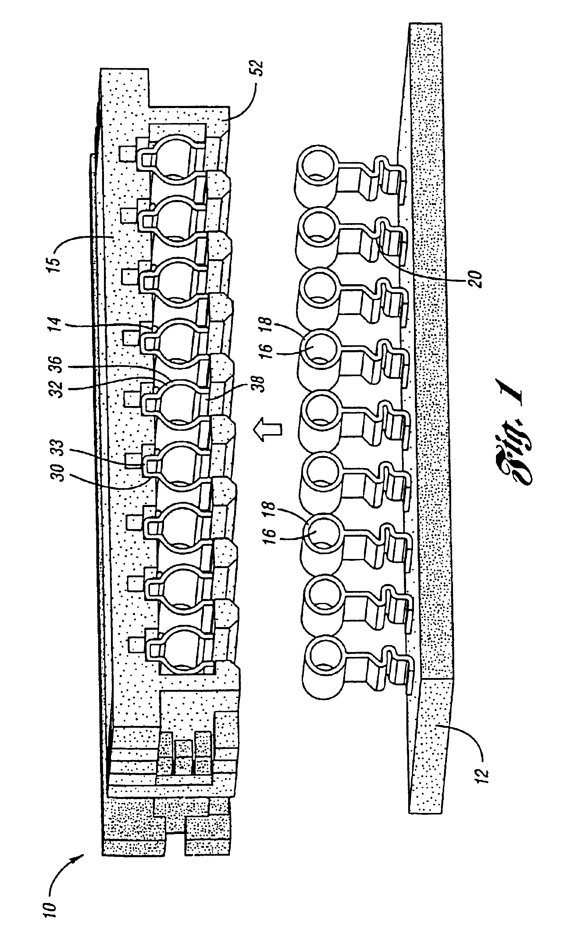
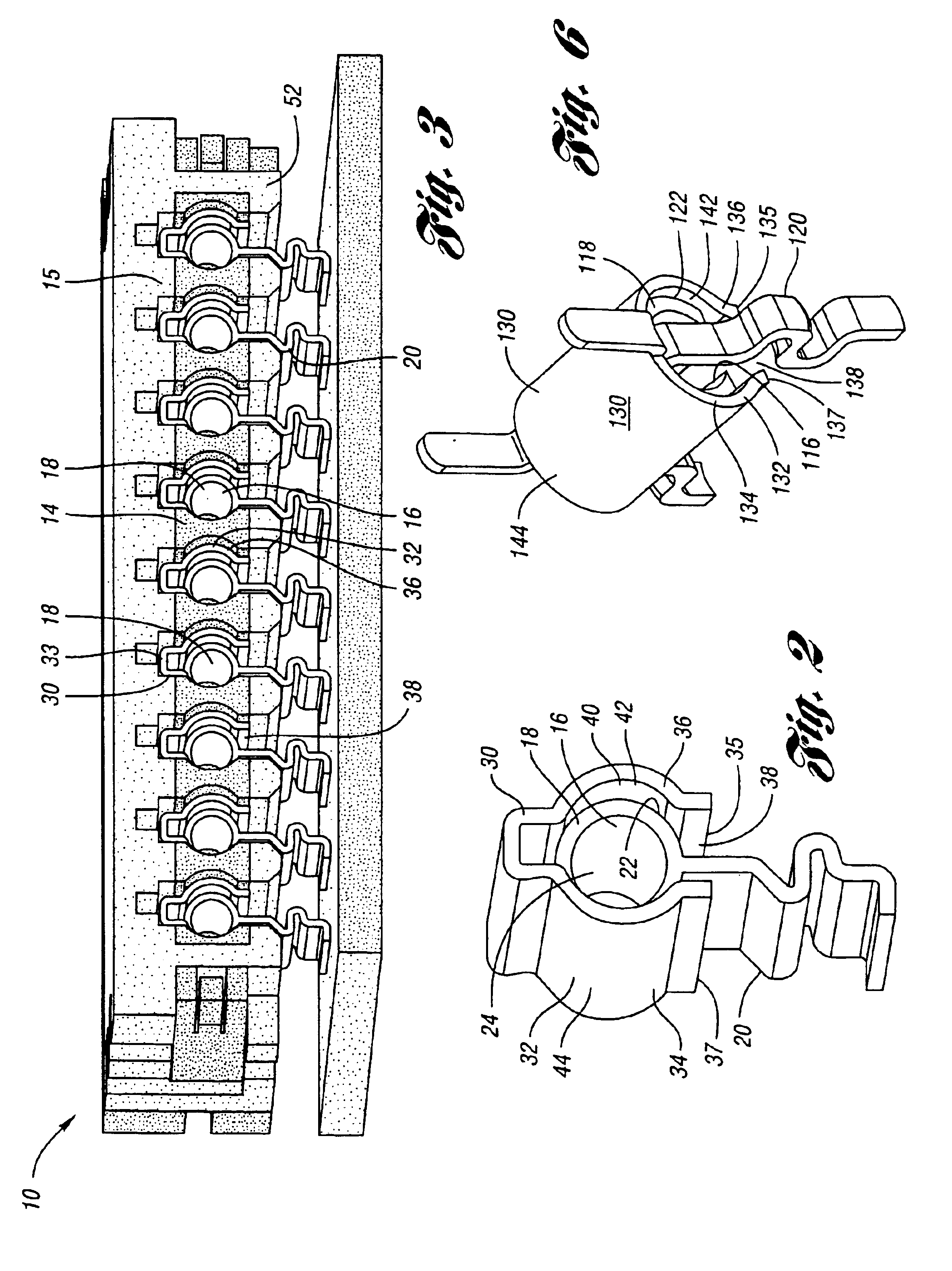
[0013]FIG. 1 illustrates one embodiment of a universal connector assembly 10 in a disengaged position for electronic interconnection. Electronic interconnection may be used in various suitable industries, especially the automotive industry. For example, the universal connector assembly 10 may be used for electrical communication between electronic systems within an instrument panel of a vehicle. This may be for a light, a time display, or an indicator as applicable.

[0014]Universal connector assembly 10 includes a printed circuit board (PCB) 12 and a connector housing 15 cooperating with a connecting member 14. Printed circuit board 12 may be any suitable circuit board used in the electronic arts. In this embodiment, connecting member 14 has one or a plurality of fingers extending therefrom to cooperate with connector housing 15 to secure electrical contacts of connector assembly 10 as described in greater detail below.

[0015]As shown in FIG. 2, connector assembly 10 further includes ...


PUM


Abstract

The present invention involves a universal connector assembly for electronic interconnection. The connector assembly includes a printed circuit board to which a male insert is in electrical communication. The male insert includes a strain relief tail connected to the printed circuit board and extends to a contact head. The assembly further includes a female socket for receiving the contact head of the male insert. The female socket has receiving members extending from a base to respective ends. The ends are biasingly spaced apart to define an opening through which the male insert is disposed for electrical contact with the female socket. The receiving members have an inside contact surface and an outside surface wherein the inside surface is configured to complement the outer contact wall of the male insert for electrical engagement when the male insert is disposed through the opening. The assembly further comprises a connector housing to which the base of the female socket is attached.

Description

BACKGROUND OF THE INVENTION[0001]The present invention relates to connector assemblies for electrical interconnection.[0002]Electrical connectors and joints are known and are widely used in several different industries for various purposes. For example, in the automotive industry, electrical connectors may be used within instrument panels of a vehicle interior panel. Electrical connectors and joints allow electrical communication between systems such as a power source and a time display. Although current electrical connectors and connector assemblies are adequate, such connectors and assemblies may be improved in different ways.[0003]For example, manufacturers of electrical connectors have been challenged in producing electrical connectors and joints which have lower electrical resistance and higher retention force. Some electrical connectors have a substantial amount of continuity resistance which lead to electrical disengagement. In some situations, electrical disengagement of con...

Claims


Application Information

Patent Timeline
Patent Type & Authority Patents(United States)
IPC IPC(8): H01R13/05H01R13/04H01R13/10H01R13/631
CPCH01R13/052H01R13/6315H01R13/10
Inventor ZHOU, HONGVAN PHAM, CUONG
Owner VISTEON GLOBAL TECH INC
Why Eureka
Try Eureka