Transmission actuator driven by an electric motor

a technology of transmission actuator and electric motor, which is applied in the direction of sliding contact bearings, mechanical equipment, bearings, etc., can solve the problems of serious spatial difficulties and relative largeness, and achieve the effect of compact space, simple and cost-effective manufacturing

Inactive Publication Date: 2005-05-17
LUK LAMELLEN & KUPPLUNGSBAU BETEILIGUNGS KG
View PDF7 Cites 42 Cited by
  • Summary
  • Abstract
  • Description
  • Claims
  • Application Information

AI Technical Summary

Benefits of technology

[0007]The present invention has the objective to provide a transmission, and further to provide an actuating device which can be i

Problems solved by technology

The worm gear mechanisms used heretofore have the disadvantage that they are relatively large and present serious spatial di

Method used


Image

  • Transmission actuator driven by an electric motor
  • Transmission actuator driven by an electric motor
  • Transmission actuator driven by an electric motor

Examples


Embodiment Construction

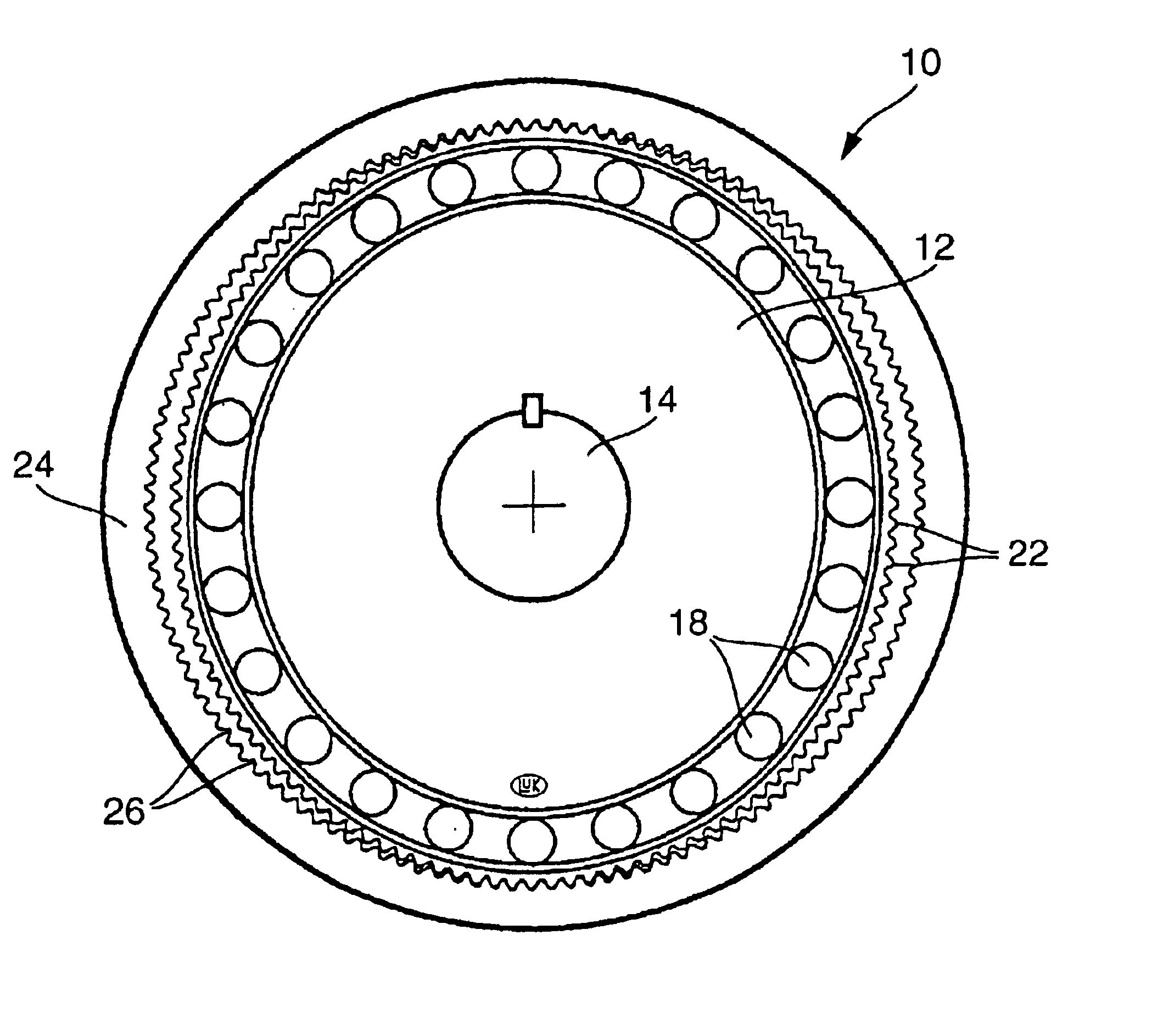
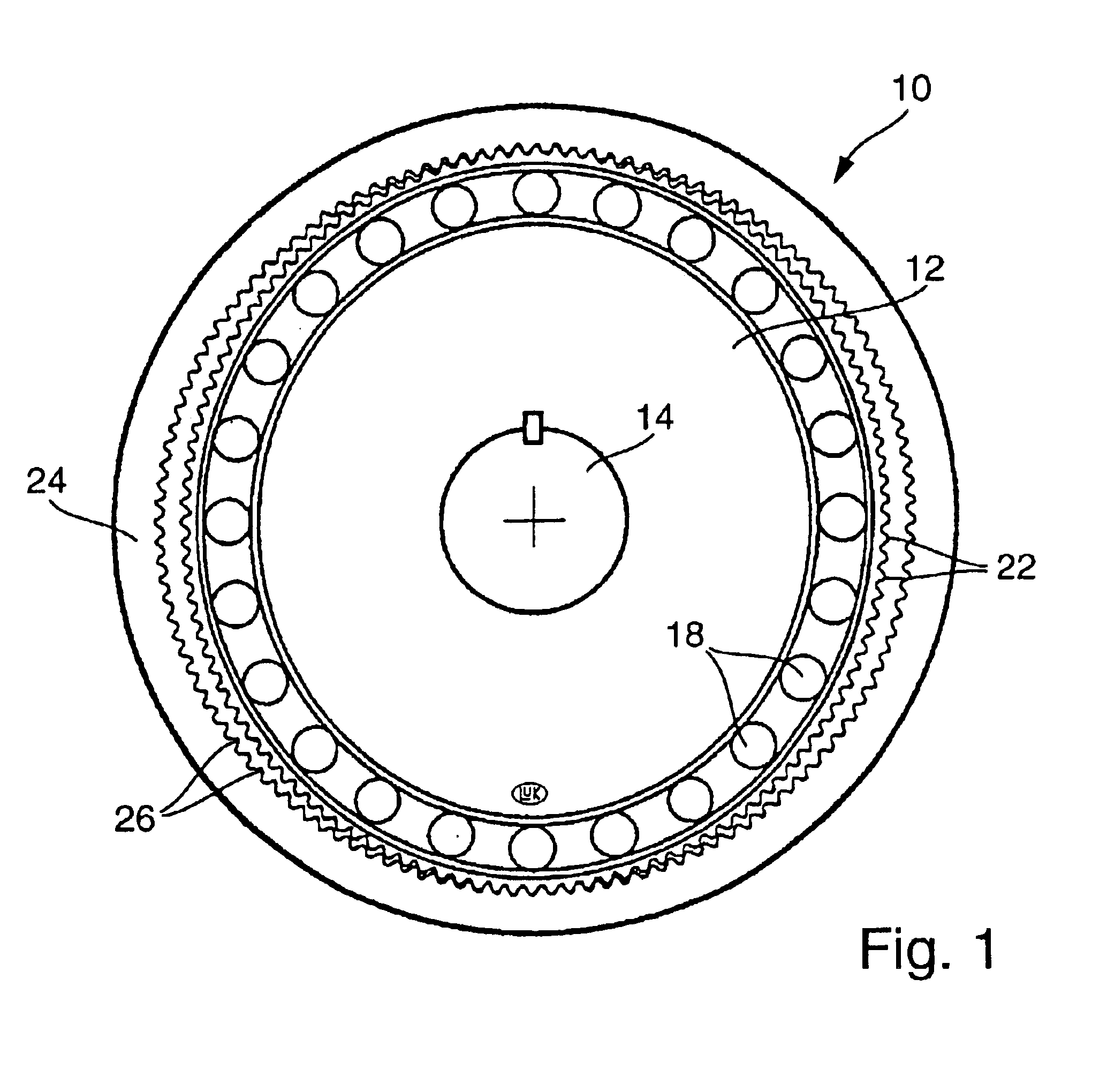
[0042]As illustrated in FIG. 1, a harmonic drive mechanism 10 as used in the electric-motor actuator of the present invention has a wave generator 12 mounted on the rotor shaft 14 of the electric motor. The wave generator 12, which is keyed to the rotor shaft 14, has an elliptical shape and carries on its outer circumference a narrow flexible roller bearing 18.

[0043]A flexible spline gear 20 is seated on the outer race of the roller bearing 18. The flexible spline gear 20 is configured as a thin band that runs in a loop and has transverse external spline teeth 22.

[0044]A rigid circular spline ring 24 with internal spline teeth is mounted non-rotatably in a concentric position with the arrangement of the wave generator 12 and the flexible spline gear 20. The circular spline ring 24 has inward-facing, axially oriented spline teeth 26. The internal diameter of the circular spline ring 24 is equal to the major axis length of the ellipse formed by the wave generator 12 carrying the flexi...


PUM


Abstract

An actuator for a motor vehicle transmission has a shift cylinder performing rotary actuating movements. An electric motor is arranged inside the shift cylinder and drives the latter either through a harmonic drive mechanism or a planetary drive mechanism. The arrangement provides a high reduction ratio and an efficient use of limited space.

Description

CROSS-REFERENCE TO RELATED APPLICATION[0001]This application is a continuation of International Patent Application Ser. No. PCT / DE 01 / 04134, filed Nov. 2, 2001, which is hereby incorporated by reference in its entirety.BACKGROUND OF THE INVENTION[0002]The present invention relates to shift-actuating members, more specifically to actuators that are driven by electric motors and are used for the control of a gear-shifting mechanism of an automatic transmission system in a motor vehicle.[0003]Electrically powered actuators used for the control of gear-shifting mechanisms of automatic transmission systems usually incorporate a worm gear mechanism in order to achieve a high reduction ratio, i.e., to change the high-rpm and relatively low-torque output of the electric motor into a relatively high torque at a low rpm-rate as required for actuating a gear-shifting mechanism. The foregoing concept is disclosed for example in GB 2325036, GB 2313885, and GB 2309761, which are hereby explicitly...

Claims


Application Information

Patent Timeline
IPC IPC(8): F16H63/08F16H61/28F16H61/32F16H63/18F16H49/00F16C27/02F16H1/28F16H1/32F16H19/04F16H25/22F16H57/02H02K7/116
CPCF16H63/18F16H61/32F16H49/001Y10T74/19279
Inventor MILLS, JOHNBOLL, BERNHARDHUSEBY, GEIRHIRT, GUNTERNORUM, VIGGOOYEN, JANLEIN, LARSBARNES, NIGELRONNE, SIMEN
Owner LUK LAMELLEN & KUPPLUNGSBAU BETEILIGUNGS KG
Why Eureka
Try Eureka