Guidewire locking device and method

a locking device and guide wire technology, applied in the field of guide wire locking device and method, can solve the problems of manual holding multiple guide wires, difficult and time-consuming procedures, and displacing guide wires,

Inactive Publication Date: 2005-05-17
BOSTON SCI SCIMED INC
View PDF7 Cites 70 Cited by
  • Summary
  • Abstract
  • Description
  • Claims
  • Application Information

AI Technical Summary

Benefits of technology

[0006]The present invention is further directed to a locking device for maintaining a position within a body lumen of a first elongate member relative to a flexible endoscope while a second elongate member is withdrawn from the body lumen, the locking device comprising a mounting mechanism for selectively coupling the locking device to a distal end of the endoscope and an angled head which, when the mounting mechanism is coupled to the endoscope in a predetermined configuration, overlies an opening at a distal end of the endoscope to a working channel of the endoscope in combination with a plurality of locking features extending from the angled head to immobilize a portion of the first elongate member relative to the endoscope and a locking arm extending from the angled head between the opening at the distal end of the endoscope and the locking features to limit movement of a portion of the first elongate member between the opening and the locking features.

Problems solved by technology

If the guide wire is displaced, the guide wire must be redirected through the body to the target area, in a difficult and time consuming procedure.
This procedure is difficult and often results in displacing the guide wire.
Manually holding multiple guide wires is extremely difficult when conventional methods and devices are used, since the surgeon has to manually hold the guide wires in place while at the same time replacing one or more catheters.

Method used


Image

  • Guidewire locking device and method
  • Guidewire locking device and method
  • Guidewire locking device and method

Examples


Embodiment Construction

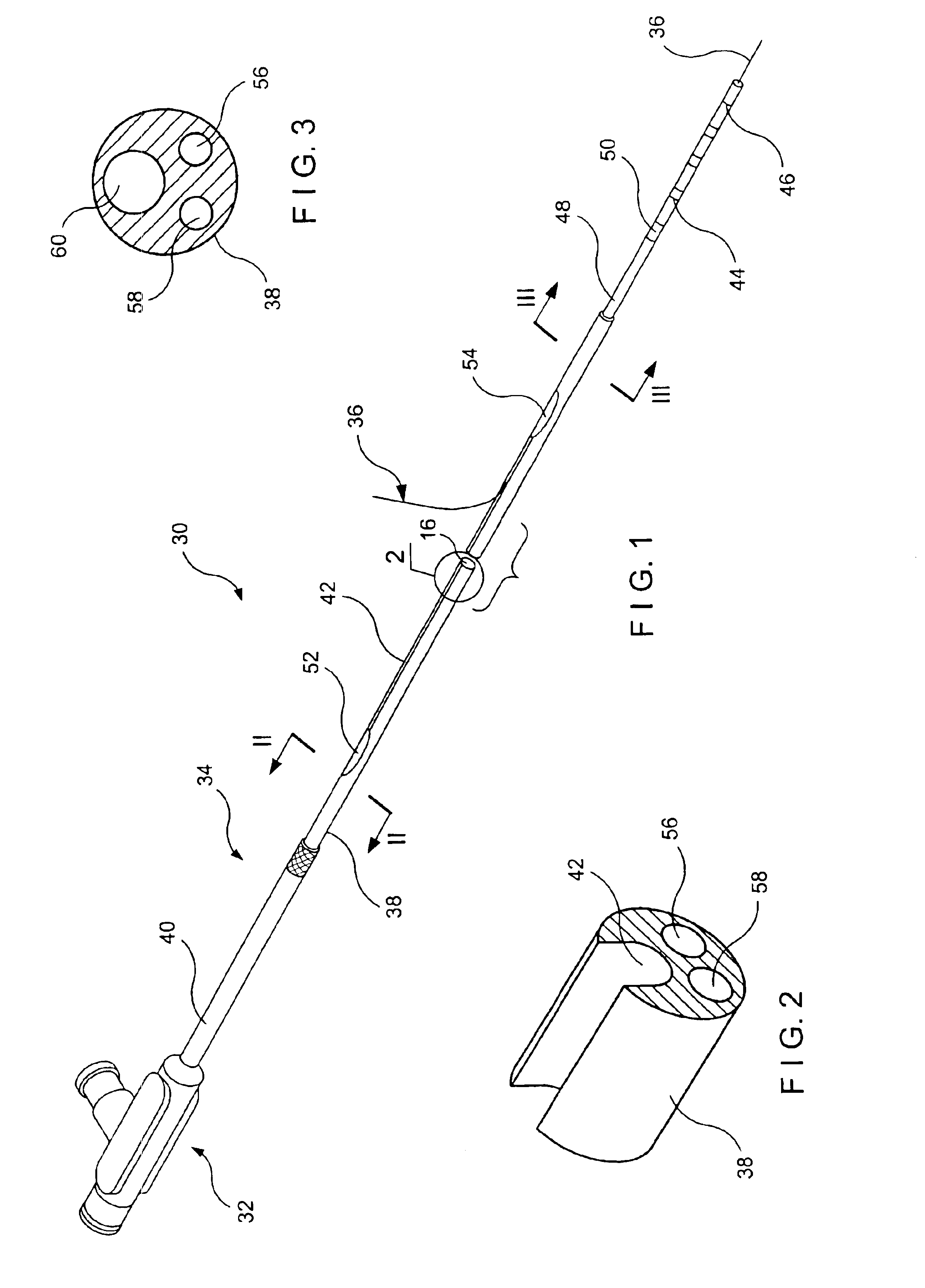
[0022]FIG. 1 shows an exemplary embodiment of a catheter assembly 30 according to the present invention for use in accessing targeted anatomical regions through, e.g., the alimentary canal. The present invention incorporates features that allow rapid exchange of one or more catheters by a single operator. The catheter of the present invention allows shorter length guide wires to be used, resulting in procedures which require fewer medical personnel, are less time consuming, and less costly. Additionally, the present invention is adaptable to a variety of devices for catheter procedures within the alimentary canal or any other body lumen.

[0023]The catheter assembly 30 includes a catheter hub assembly 32 and a catheter 34 with a guide wire lumen 60 extending therethrough. As shown in FIGS. 2 and 3 a guide wire 36 may be inserted therein. The catheter 34 includes a shaft 38 which has a proximal end 40, a channel 42, a distal tip region 44, a distal end 46 and several internal lumens de...


PUM


Abstract

A locking device for a maintaining an elongated member at a selected place within a body lumen comprises a substantially rigid body including an attachment portion adapted to be coupled to a distal portion of a medical instrument wherein, when in an operative position, the distal portion of the medical instrument is received within the body lumen and an angled head coupled to the substantially rigid body, the angled head being configured to overlie an access port of the medical device when the attachment portion is coupled to the distal portion of the medical device in a predetermined configuration in combination with a plurality of locking features extending from the angled head to immobilize a section of the elongated member relative to the medical device and a locking arm extending from the locking device so that, when the attachment portion is coupled to the medical device, the locking arm extends between the access port and the locking features to guide the elongated member from the access port to the locking features along a desired path.

Description

BACKGROUND INFORMATION[0001]Endoscopic procedures to treat abnormal pathologies of the alimentary canal and the biliary tree are becoming increasingly common. Endoscopes are often used in these procedures to facilitate access to biliary, hepatic and pancreatic ducts, in addition to the larger alimentary passages. The endoscope itself can only provide access to the general area adjacent to the smaller ducts and navigation of the ducts themselves must be carried out using smaller devices, such as catheters and guide wires in conjunction with fluoroscopy. Targeted delivery of therapeutic agents and surgical procedures within the ducts is typically carried out using catheters.[0002]Methods and devices for using catheters to access the biliary tree are described in U.S. Pat. No. 5,397,302 to Weaver et al., and in U.S. Pat. No. 5,320,602 to Karpiel, the disclosures of which are herein incorporated by reference in their entirety. In a general process, treatment of a patient's biliary tree ...

Claims


Application Information

Patent Timeline
Patent Type & Authority Patents(United States)
IPC IPC(8): A61B1/012A61B1/018A61M25/09A61M25/18
CPCA61M25/09041A61M25/02A61B1/018A61M2025/09125
Inventor CARRILLO, OSCAR
Owner BOSTON SCI SCIMED INC
Why Eureka
Try Eureka