Knee prosthesis

a prosthesis and knee technology, applied in the field of knee prosthesis, can solve the problems of total absence of antero-posterior movement freedom between the femoral bones, rapid degradation of polyethylene, and inability to respect the mechanism of rolling/sliding, so as to reduce the

Inactive Publication Date: 2005-05-17
BERCOVY MICHEL
View PDF15 Cites 229 Cited by
  • Summary
  • Abstract
  • Description
  • Claims
  • Application Information

AI Technical Summary

Benefits of technology

[0047]In the concept proposed according to the invention, the resultant of the transmissions of the stresses is preferably directed to the central part of the tibial seat, about its central element of fixation which is called a stem and is fitted at the center of the upper end of the tibial bone. The aim of this type of transmission is to reduce as much as possible the medio-lateral torque effect which is responsible for the loosening or for predominant wear of one of the two compartments.

Problems solved by technology

This leads to rapid degradation of the polyethylene, possibly necessitating further surgery to change the prosthetic implants.
A disadvantageous effect of this latter configuration is a total absence of freedom of antero-posterior movement between the femoral component and the tibial insert when the cylinder has the same transverse axis as the two lateral condyles.
The mechanism of rolling / sliding is not respected and one of the consequences can be the existence of considerable patellar pain.
The recovery of a certain forward / rearward mobility in the zone of contact between polyethylene insert and tibial plateau is not sufficient to overcome this disadvantage; this mobility situated at a different level than normal generates a parasite movement referred to as “roll forward”, during which the tibia moves back in flexion relative to the femur, which can lead to disengagement of the prosthetic components.
However, the engagement of this device in the frontal plane reproduces a broken curve, a source of shocks, of angular contact (edge contact), sudden stops, and, thus, mechanisms which can cause loosening of the prosthesis.
However, in these designs, the different sagittal planes (in the plane XY) are offset in relation to one another, which, when seen from the front, translates into a broken line which is likely to generate high stress peaks in the polyethylene, as well as transmission of abnormally high stresses, shocks and vibrations to the sites of fixation of the prosthesis during movements of lift-off / lateral inclination.
Since the mechanical axis of the body running from the center of gravity of the body to the contact of the foot with the ground passes medially in relation to the knee joint, the bearings on both the medial and lateral compartments of the knee are asymmetrical, creating several sources of problems.
For this reason, the external compartment of the knee tends to lift at the level of its tibial fixation and lead to a possibility of separating of the latter, the source of mobilization of the prosthesis, which can result in deterioration and a new surgical procedure.
Another source of problems lies in the fact that, between the bearing phase and the oscillating phase of walking, there is a separating of the femoral metal component relative to the polyethylene insert, which in English is referred to by the term lift-off.

Method used


Image

  • Knee prosthesis
  • Knee prosthesis
  • Knee prosthesis

Examples


Embodiment Construction

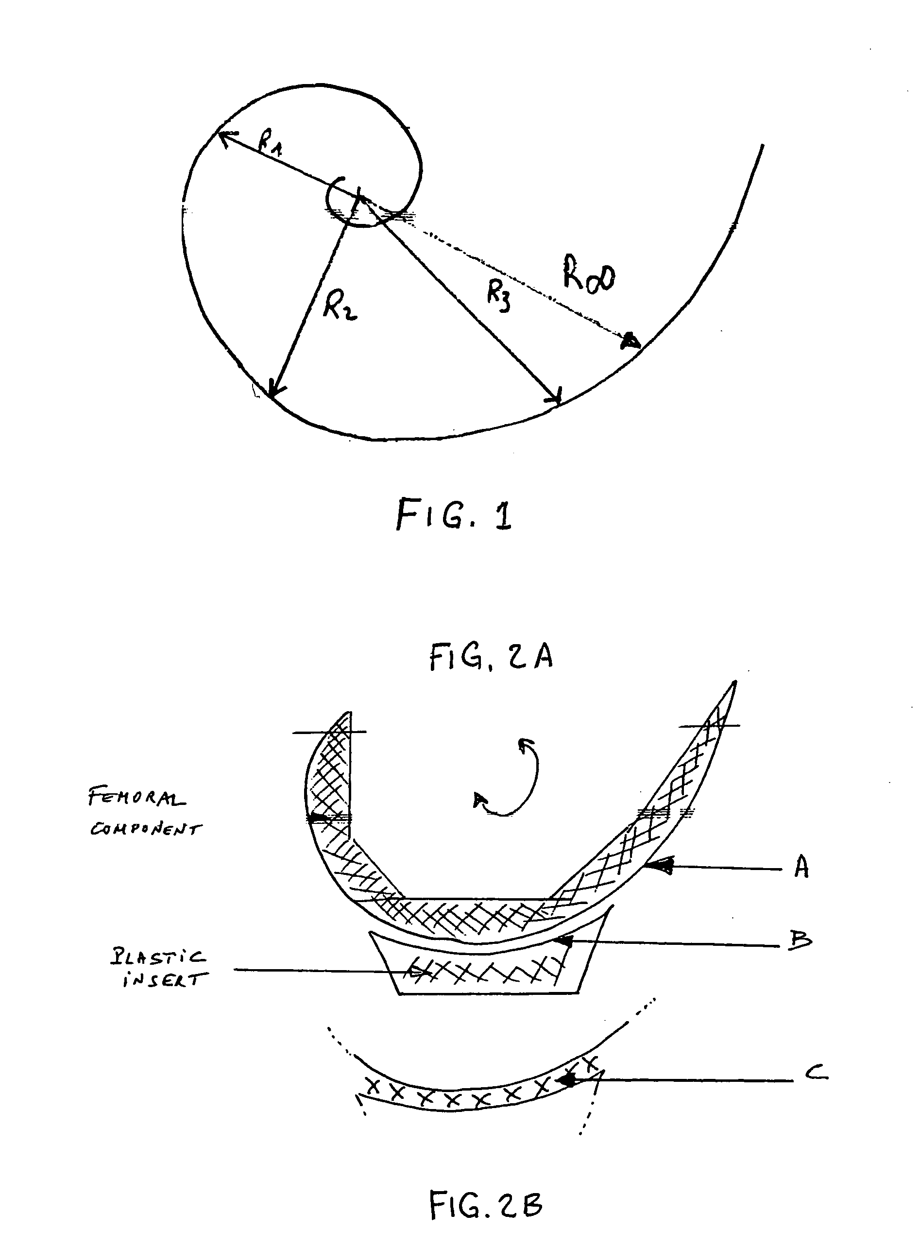
[0093]The knee prosthesis illustrated in FIG. 1 comprises a femoral component 1 which is generally of metal and can be implanted in the femur of the patient, a tibial component 2 which is also of metal and can be implanted in the tibia of the patient, and an insert 3 which is generally of a plastic material such as polyethylene.

[0094]The insert 3 bears on a plateau 4 of the tibial component 2 and can be fixed in position on the latter or, as is shown in the drawing, can be movable in rotation relative to the plateau 4 about an axis which, in the position of use of the prosthesis, is disposed vertically. For this purpose, the insert 3 here comprises, projecting from its surface directd toward the component 2, a stud 5 which is engaged in a hollow central stem 6 of the tibial component 2, in a manner known per se.

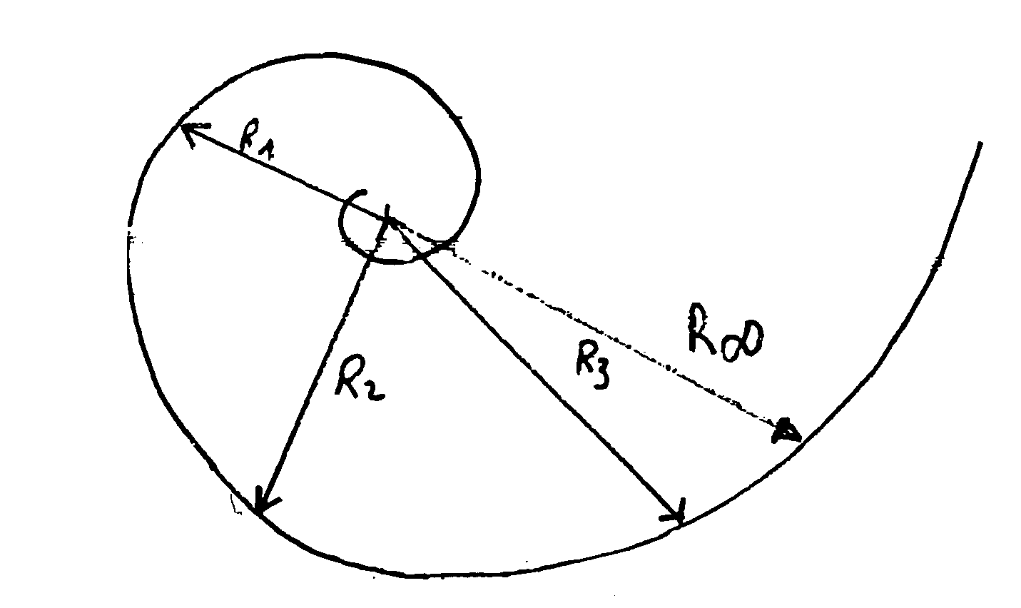
[0095]In a conventional manner, the femoral component 1 comprises two lateral condylar parts 7 whose cross section, through a sagittal plane, has the form of a spiral, the ex...


PUM


Abstract

The invention concerns a prosthesis wherein the contact surfaces of the femoral part (i), the insert (3) and the knee joint are defined by the combination of two curves, a spiral-type curve in the saggital plane following an undulating curve (sinusoidal) in the frontal plane. The latter comprises two concave lateral parts and a central dome-shaped convex part, the three parts being connected without any angulation, protuberance, or flat parts or bends and providing continuous medio-lateral contact on the three zones, from complete extension to complete bending, and a concave-convex nesting in the central zone.

Description

BACKGROUND OF THE INVENTION[0001]1. Field of the Invention[0002]The present invention relates to a novel prosthesis for the knee joint. This prosthesis is more particularly intended to include an arrangement comprising means for optimum contact, stabilization and guidance between the movable components during movements in three directions.[0003]It will be recalled that a knee prosthesis is an implant intended to surgically replace a destroyed knee joint.[0004]A knee prosthesis includes elements integral with the bone, and generally made of metal, and sliding elements, generally made of a plastic material such as polyethylene. The metal elements are:[0005]a femoral component which more or less reproduces the form of the femoral articulation of the knee; it is fixed to the bone, either directly via a rehabilitation surface, or indirectly by means of an acrylic resin;[0006]a tibial surface fixed to the upper end of the tibia, either directly, or by means of an acrylic resin; and[0007]a...

Claims


Application Information

Patent Timeline
Patent Type & Authority Patents(United States)
IPC IPC(8): A61F2/38A61F2/00A61F2/30
CPCA61F2/3868A61F2/3859A61F2/389A61F2002/30332A61F2002/30364A61F2310/00011A61F2002/30878A61F2002/30945A61F2220/0025A61F2220/0033A61F2002/30518A61F2002/30943
Inventor BERCOVY, MICHEL
Owner BERCOVY MICHEL
Why Eureka
Try Eureka