Safety outlet module

a safety outlet and module technology, applied in the direction of insulated conductors, coupling device connections, cables, etc., can solve the problems of shock and fire hazards, standard electrical wiring repair, etc., to reduce exposure to electrical wiring, easy and safe replacement of outlet and switch modules, and enhanced safety

Inactive Publication Date: 2005-05-17
BAUM FAMILY TRUST DTD 1 11 2001 +143
View PDF36 Cites 58 Cited by
  • Summary
  • Abstract
  • Description
  • Claims
  • Application Information

AI Technical Summary

Benefits of technology

[0005]Removable functional modules configured to be plugged into or unplugged from a wiring module benefit electrical contractors and users alike. Such modules may include switch modules, modules having conventional outlets, or safety outlet modules with covered receptacles, to name a few. Homeowners can easily and safely replace broken outlet and switch modules by simply unplugging such modules from the wiring module, without exposure to power cabling. Safety is enhanced by reducing exposure to electrical wiring and encouraging replacement of defective outlets and switches. Further, maintenance costs are reduced by reducing the need to hire an electrician for repairs. Wiring integrity is insured by reducing the opportunity for unqualified third parties to access the electrical system.

Problems solved by technology

From a user's perspective, there are problems with repair of the standard electrical wiring.
This exposure creates a shock hazard.
Further, a user's reluctance to change out broken outlets or switches or to spend the money to hire an electrician also creates a shock and a fire hazard from continued use of cracked, broken or excessively worn assemblies.
In addition, the integrity of the original wiring becomes questionable if a homeowner or other third party removes and replaces an outlet or switch.
Miswiring by a third party can violate building codes and create shock and fire hazards, such as inadvertently switching the hot and neutral conductors, failing to attach ground wires, kinking or nicking conductors and improperly tightening connections.
These plugs, however, significantly reduce outlet convenience.
Standard AC plugs also create a shock hazard due to their tendency to pull partially out of an outlet, leaving exposed prongs that remain connected to electrical power.
Further, in research, industrial or military environments, an explosion hazard exists when electrical outlets are used in the vicinity of volatile chemicals and gases, which can be ignited with an inadvertent spark at an exposed contact.

Method used


Image

  • Safety outlet module
  • Safety outlet module
  • Safety outlet module

Examples


Embodiment Construction

Overview

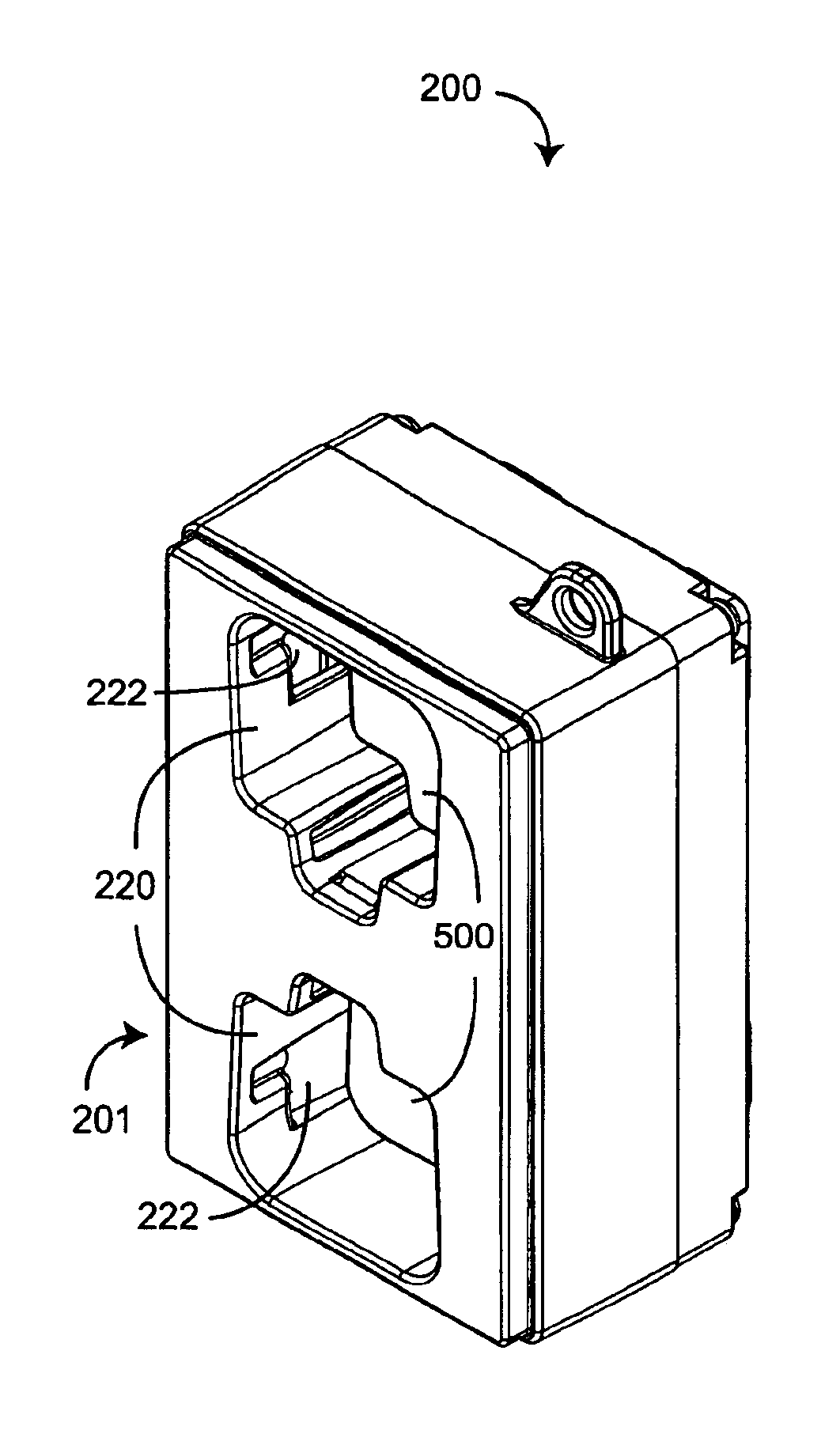
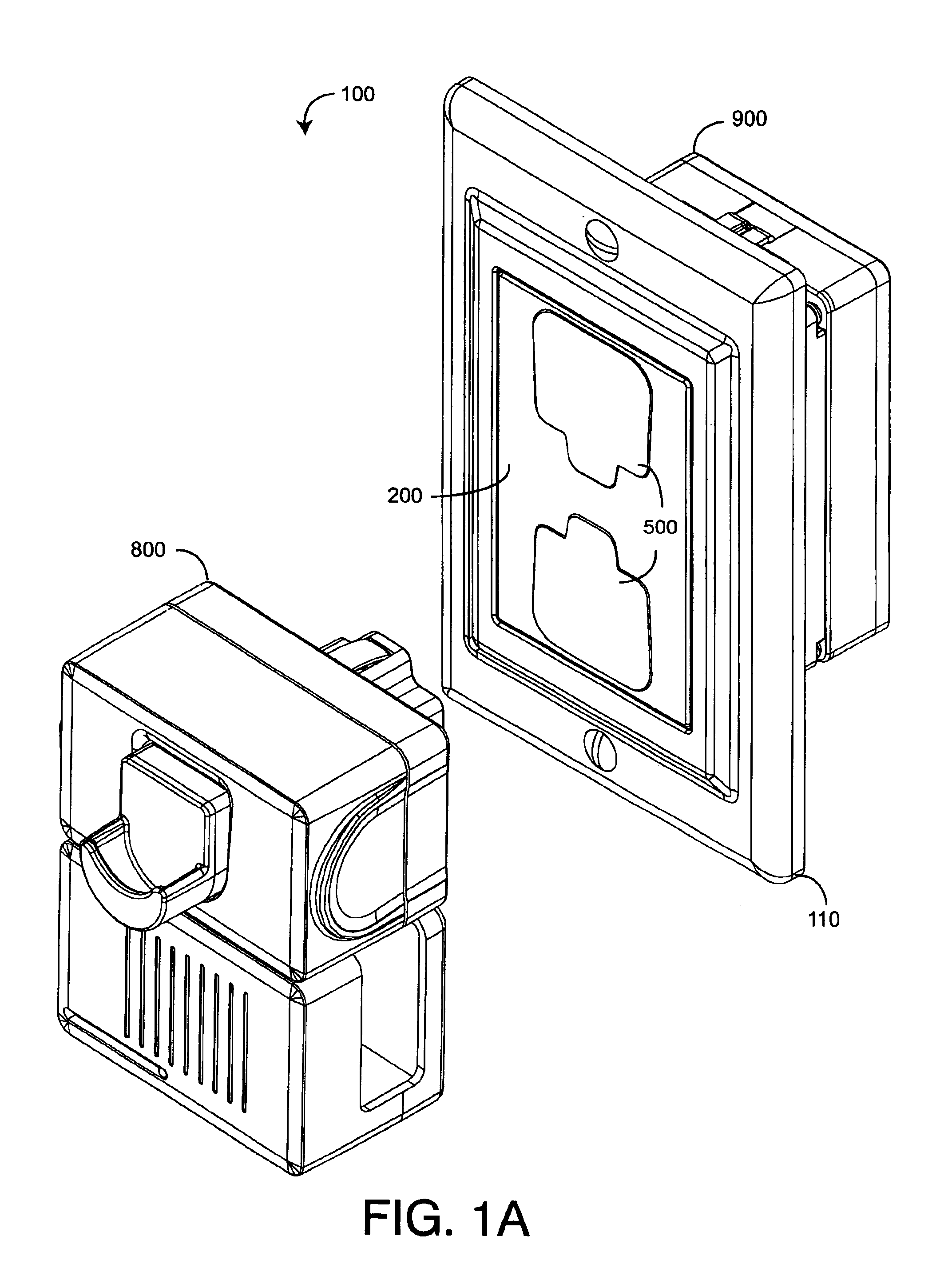
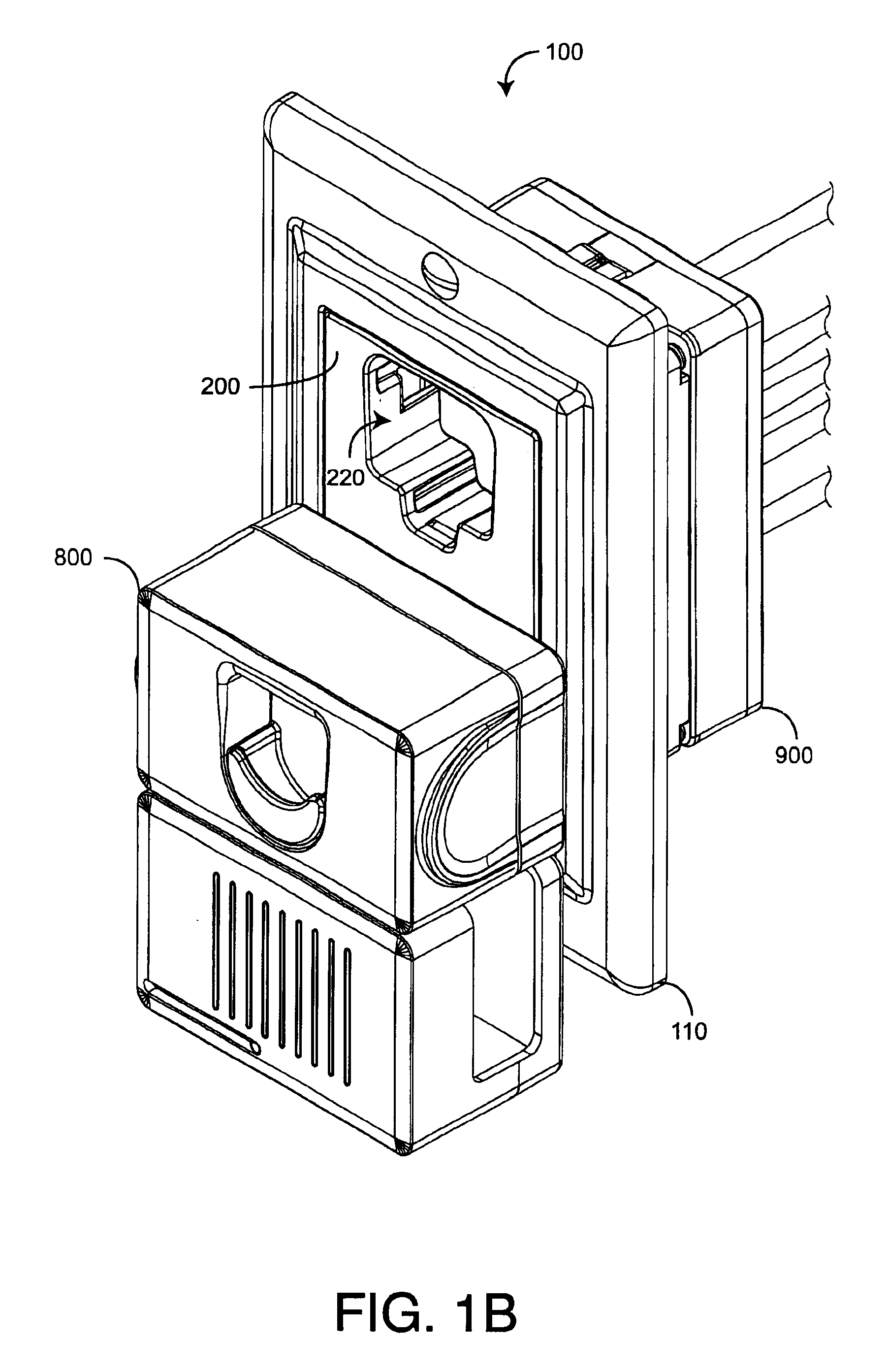
[0028]FIGS. 1A-D illustrate a safety power distribution system 100 having a safety outlet module 200, a corresponding locking plug 800 and wiring module 900. The safety outlet module 200 is configured to removably plug into the wiring module 900 and, thus, advantageously provides the safety and convenience features of a replaceable functional module, as described above. Further, the outlet module 200 has spring-loaded covers 500 that block small children from probing the outlet receptacles 220 with fingers and foreign objects, yet allows adults to insert the locking plug 800 without cover removal. Internally, outlet receptacles 220 have no exposed contacts, further reducing the potential for electrical shock. A face plate 110 provides aesthetic wall trim for the outlet module 200. The locking plug 800 is configured to compress the receptacles covers 500 when inserted into the outlet module 200. The locking plug 800 has retracting prongs 832 (FIGS. 8A-D) that extend within th...


PUM


Abstract

A safety outlet module includes a housing, a receptacle defined by the housing, an aperture defined within the receptacle, a cover slidably retained within the receptacle and a plug retained at least partially within the housing. The receptacle has an opening, a bottom and a wall extending between the opening and the bottom. The aperture partially extends along the wall. The cover has a closed position proximate the opening and an open position proximate the bottom. The aperture is blocked in the closed position and exposed in the open position. The plug extends from a housing face and is adapted to removably connect to an electrical power source. A contact is retained by the housing outside of the receptacle and proximate to the aperture, and a buss internal to the housing connects the plug to the contact.

Description

CROSS-REFERENCE TO RELATED APPLICATIONS[0001]This application relates to and claims the benefit of prior U.S. Provisional Application No. 60 / 434,002 entitled Safety Plug and Covered Outlet Module, filed Dec. 16, 2002, incorporated by reference herein.BACKGROUND OF THE INVENTION[0002]Standard AC electrical distribution systems are comprised of electrical boxes mounted within building walls at various locations, along with switch and outlet assemblies installed within the boxes. During a roughing phase of construction, the electrical boxes are mounted to wall studs at predetermined locations. After the boxes are installed, a journeyman electrician routes power cables through building framing to the appropriate boxes. The power cables are fed through openings in the rear or sides of the electrical boxes and folded back into the boxes, unterminated, so as to be out of the way until the next phase. During a makeup phase, wall panels are installed and painted, and the journeyman returns t...

Claims


Application Information

Patent Timeline
Patent Type & Authority Patents(United States)
IPC IPC(8): H02G3/08H01R13/44H01R13/447H01R13/713
CPCH01R13/447H01R13/713H01R13/655H01R2103/00H01R24/78
Inventor GORMAN, MICHAEL P.
Owner BAUM FAMILY TRUST DTD 1 11 2001
Why Eureka
Try Eureka