AI technical title is built by Patsnap AI team. It summarizes the technical point description of the patent document.
a technology of generators and generators, applied in the direction of magnetic circuits, emergency protective arrangements for automatic disconnection, insulated cables, etc., can solve the problems of complicated winding work, less satisfactory coil ends, and extra cost for transformers, and achieve the effect of low stray losses
Inactive Publication Date: 2005-05-17
ABB (SCHWEIZ) AG
View PDF752 Cites 19 Cited by
Summary
Abstract
Description
Claims
Application Information
AI Technical Summary
This helps you quickly interpret patents by identifying the three key elements:
Problems solved by technology
Method used
Benefits of technology
Benefits of technology
[0013]The fact that the solid insulation enables the windings to be arranged for direct connection to the high-voltage network, thus eliminating the step-up transformer, offers great advantages over known technology.
[0044]The solid insulation in a generator according to the invention also offers great advantages when constructing a hydro-generator plant. The absence of wet insulation means that the stator of the generator need not be completed at the factory but can instead be delivered in parts and assembled on site. A stator of the size under consideration here is large and heavy which has entailed transport problems with conventional designs where the roads must be reinforced and dimensioned for the vast weight. This problem is eliminated since the stator for a generator can be delivered in parts.
Problems solved by technology
If there are more than two layers these crossings complicate the winding work and the coil end is less satisfactory.
However, the machine designs according to the above publications do not permit optimal utilization of the electromagnetic material in the stator.
Method used
Image
Click on the blue label to locate the original text in one second.
Reading with bidirectional positioning of images and text.
Examples
Embodiment Construction
[0010]The object of the invention is thus to provide an electric generator which can be used in a hydro-generator plant for such high voltage that the above-mentioned Δ / Y-connected step-up transformer can be omitted, i.e. a plant in which the electric generators are intended for considerably high voltages than conventional machines of corresponding type, in order to be able to execute direct connection to power networks at all types of high voltage.
[0011]This object has been achieved according to the invention in that a plant of the type described in the preamble to claim 1 is given the special features defined in the characterizing part of this claim, in that a generator of the type described in the preamble to claim 34 is given the special features defined in the characterizing part of this claim, and in that a procedure of the type described in the preamble to claim 33 includes the special measures defined in the characterizing parts of respective claims.
[0012]Thanks to the solid...
PUM
Property
Measurement
Unit
diameter
aaaaa
aaaaa
diameter
aaaaa
aaaaa
area
aaaaa
aaaaa
Abstract
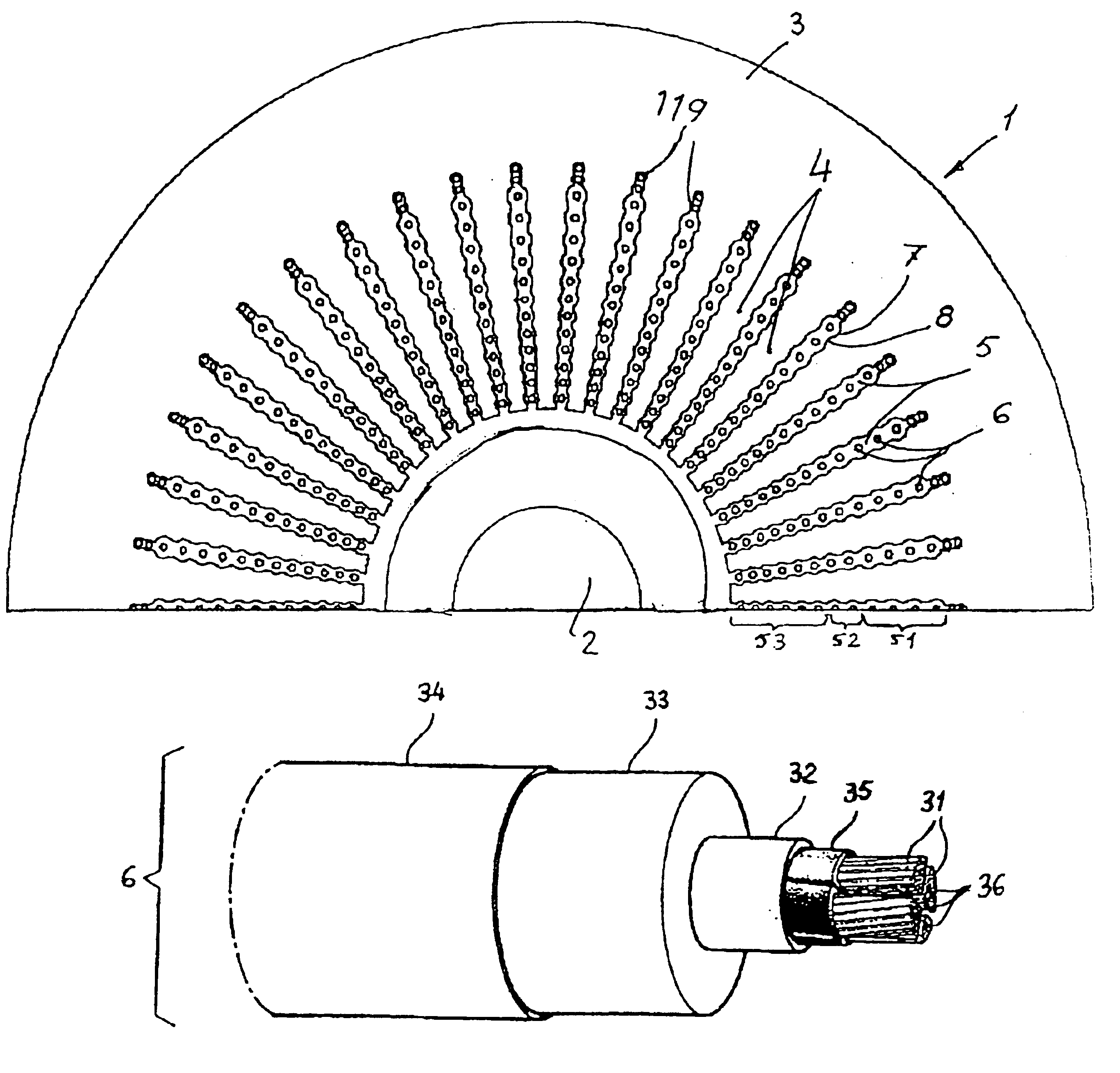
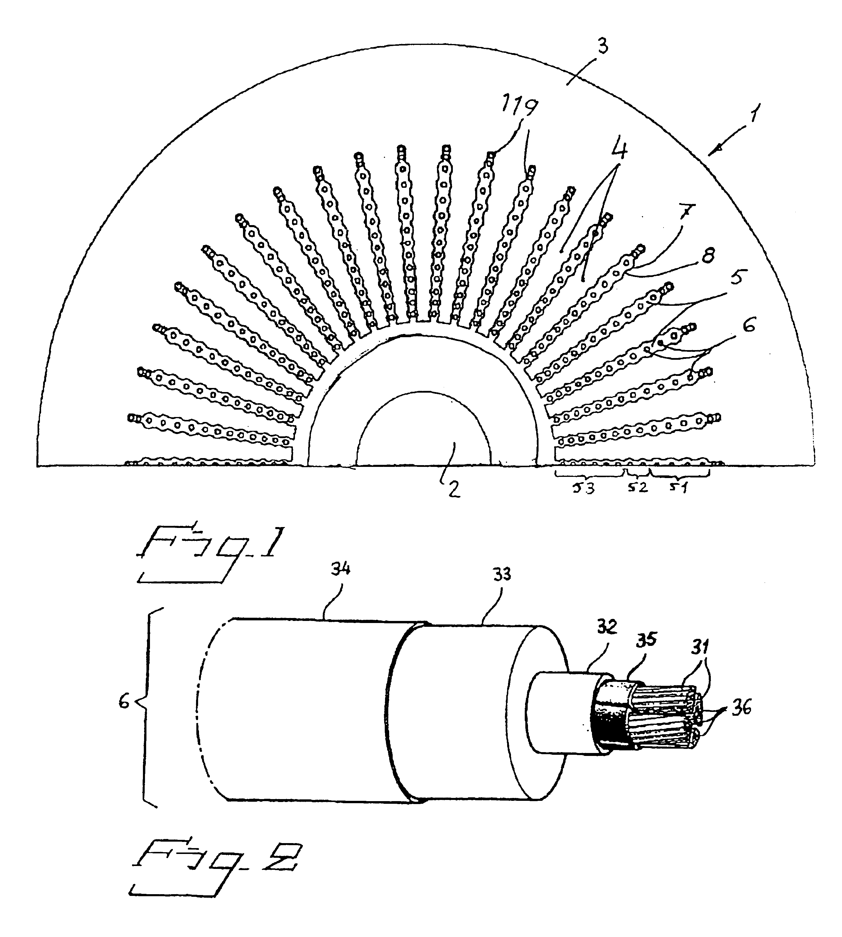
The magnetic circuit of a generator in a hydro-generator plant is arranged to directly supply a high supply voltage of 20-800 kV, preferably higher than 36 kV. The generator is provided with solid insulation and its winding includes a cable (6) comprising one or more current-carrying conductors (31) with a number of strands (36) surrounded by at least one outer and one inner semiconducting layer (34, 32) and intermediate insulating layers (33). The outer semiconducting layer (34) is at earth potential. The stator winding may be produced with full or fractional slot winding, the phases of the winding being Y-connected. The Y-point may be insulated and protected from over-voltage by means of surge arresters, or else the Y-point may be earthed via a suppression filter. The invention also relates to a hydro-generator plant, a generator included in the plant and a procedure for building such a plant.
Description
TECHNICAL FIELD[0001]The present invention relates to a hydro-generator plant of the type described in the preamble to the claim and which is intended for connection to distribution or transmission networks, hereinafter called power networks. The invention also relates to an electric generator for high voltage in a hydro-generator plant intended for the above-mentioned purpose. The invention further relates to a procedure for assembling such a plant and the manufacture of such a generator.BACKGROUND ART[0002]The magnetic circuits in electric generators usually comprise a laminated core, e.g. of sheet steel with a welded construction. To provide ventilation and cooling the core is often divided into stacks with radial and / or axial ventilation ducts. For larger machines the laminations are punched out in segments which are attached to the frame of the machine, the laminated core being held together by pressure fingers and pressure rings. The winding of the magnetic circuit is disposed...
Claims
Application Information
Patent Timeline
Application Date:The date an application was filed.
Publication Date:The date a patent or application was officially published.
First Publication Date:The earliest publication date of a patent with the same application number.
Issue Date:Publication date of the patent grant document.
PCT Entry Date:The Entry date of PCT National Phase.
Estimated Expiry Date:The statutory expiry date of a patent right according to the Patent Law, and it is the longest term of protection that the patent right can achieve without the termination of the patent right due to other reasons(Term extension factor has been taken into account ).
Invalid Date:Actual expiry date is based on effective date or publication date of legal transaction data of invalid patent.

