Method and apparatus for bringing laser chips to a measurement position

Inactive Publication Date: 2005-05-17
TELEFON AB LM ERICSSON (PUBL)
View PDF4 Cites 0 Cited by
  • Summary
  • Abstract
  • Description
  • Claims
  • Application Information

AI Technical Summary

Benefits of technology

[0006]By the method and the apparatus according to the invention, the process of locating the point of maximum o

Problems solved by technology

This is a time consuming process in that the location of the point of

Method used


Image

  • Method and apparatus for bringing laser chips to a measurement position
  • Method and apparatus for bringing laser chips to a measurement position

Examples


Example

DETAILED DESCRIPTION OF THE DRAWINGS

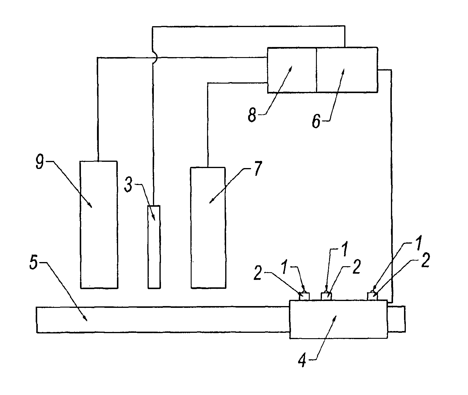
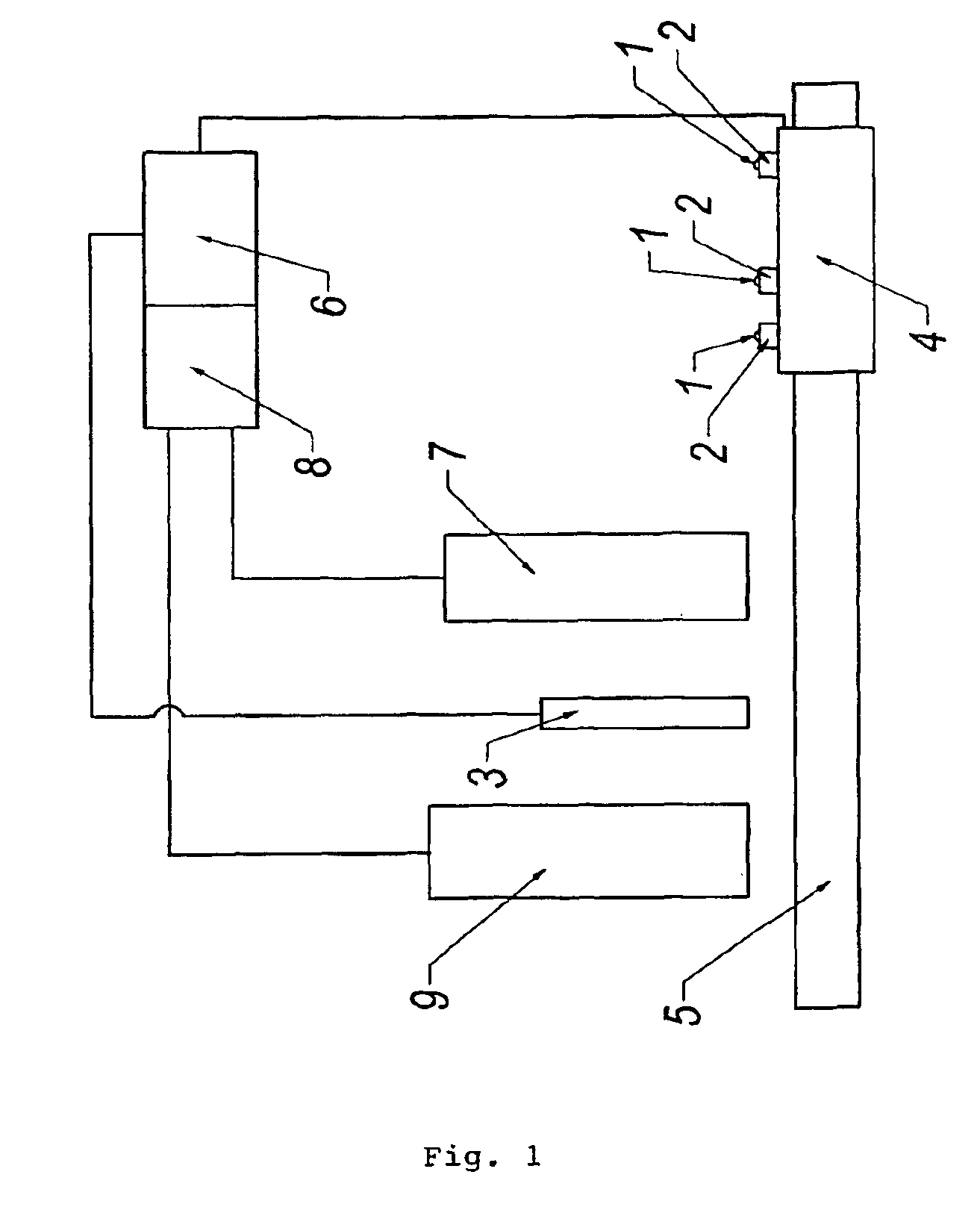
[0008]FIG. 1 is a schematic illustration of an embodiment of an apparatus for bringing laser chips 1 mounted on respective carriers 2 to a measurement station 3 to measure output light intensity of the chips 1.

[0009]In a manner known per se, the carriers 2 with the chips 1 are mounted on a fixture 4, and the fixture 4 is moved to in turn bring the chips 1 to the measurement station 3.

[0010]In the embodiment shown, the fixture 4 is driven by means of a motor (not shown), e.g. a linear motor, along a rod 5 under control of a central control and signal processing unit 6.

[0011]In accordance with the invention, the fixture 4 is first moved along the rod 5 to bring the first chip 1 in front of a TV camera 7. The TV camera 7 is connected to a vision system 8 that is adapted to determine x and y coordinates of objects viewed by the TV camera 7, and that is connected to the central control and signal processing unit 6.

[0012]By means of the vision system 8,...


PUM


Abstract

An apparatus for measuring output light intensity from laser chips mounted on respective carriers on a fixture, comprises a control unit for moving the fixture to in turn bring the chips to a measurement station, and a TV camera and a NIR camera both connected to a vision system for determining x and y coordinates of objects viewed by the TV camera and the NIR camera, respectively. The control unit is adapted to move the fixture to bring the respective chip in front of the TV camera to determine the coordinates of the chip on the fixture, move the fixture in response to the coordinates of the chip on the fixture to bring the chip in front of the NIR camera to determine the coordinates of a point of maximum light intensity from the ignited chip, and move the fixture in response to the coordinates of the point of maximum light intensity to bring the chip to the measurement station.

Description

TECHNICAL FIELD[0001]The invention relates generally to laser chips and more specifically to a method and an apparatus for bringing a population of manufactured laser chips to a measurement position to select good laser chips, i.e. laser chips that fulfil an output light intensity requirement.BACKGROUND OF THE INVENTION[0002]Manufactured laser chips are mounted on carriers. To test whether or not the laser chips fulfil the requirement on output light intensity, the carriers with the chips are placed on a fixture that is moved to in turn bring the chips to a measurement station. This is a time consuming process in that the location of the point of maximum output light intensity of a laser chip on a carrier is unknown. Therefore, at the measurement station, each chip has to be scanned in order to locate the point of maximum output light intensity before the light intensity can be measured. If for some reason a chip is missing in its expected position on the fixture, the scanning for t...

Claims


Application Information

Patent Timeline
IPC IPC(8): G01J1/42H01S5/00G01R31/26
CPCG01J1/42H01S5/0014
Inventor WEST, ROLANDJENSEN, MATS
Owner TELEFON AB LM ERICSSON (PUBL)
Why Eureka
Try Eureka