Optical ring transmission system using squelch method

a transmission system and optical transmission technology, applied in the field of optical transmission apparatus and optical transmission method for ring transmission system, can solve the problems of inability to save optical signal, inability to perform squelching, and inability to connect, so as to achieve efficient information transmission, improve line utilization and line failure restoration rate, and reduce the effect of rip

Inactive Publication Date: 2005-05-17
FUJITSU LTD
View PDF6 Cites 26 Cited by
  • Summary
  • Abstract
  • Description
  • Claims
  • Application Information

AI Technical Summary

Benefits of technology

[0139]The second object of this invention is to create a squelch table at a high speed using existing hardware to enable effective information transmission, and to efficiently create an RIP table having a larger information quantity than the squelch table.
[0166]Accordingly, even when a special line failure occurs, restoration of optical signals can be controlled.

Problems solved by technology

For this, line switching may cause a connection (misconnection) that an optical signal is inadvertently transmitted over the plural lines since the protection line accommodates a plurality of lines.
When saving the optical signal is impossible, squelching is performed.
Namely, when a failure occurs in the working line involving the primary node, the secondary node continuously executes the add / drop control on the protection line.
Namely, in the case of the DCP connection or the DTP connection, an increase in number of nodes relating to a path makes it difficult to express crossconnection information by only the above squelch tables.
The optical signals are transmitted for a distance equal to a round-trip between Hawaii and a position at which the failure has occurred (failure position), so that a loss of the optical signal generates due to an excessive path when the optical signal is looped back.
This causes that other optical signal cannot use the same channel on the working line, which in turn causes a decrease in coefficient of line utilization.
It is therefore impossible to use a flag or the like to transmit information in order to notify of the working line and a use span at the secondary node, so that information used to normally carry out a switching process cannot be notified.
In addition, when a failure occurs while a data link is under establishment, each node cannot know that the data link is not transmitted beyond a certain node.
As a result, six problems arise as follows: First, when each node creates a squelch table and an RIP table and carries out crossconnect-setting in the DCP connection and the DTP connection, values of the data link are always varied.
In this case, the terminal node has to create a squelch table without using a node ID of its own in some occasion, thus cannot clearly determine whether the data link is completed or not.
The current manner has a problem that each node cannot notify of a state of setting of the protection bandwidth.
Second, the RIP table and the squelch table are incompatible although having similar features.
Hardware of these optical transmitting apparatus is suited to create the squelch tables, but not suited to create the RIP table having a large amount of information.
However, a new apparatus is sometimes connected to an old one in a ring system; it is impossible to newly produce the hardware.
Third, a meaningless value does not exist among values that can be expressed with four bits even when information on two or more nodes is attempted to be notified a secondary node, so that it is impossible to notify of which value indicates which in information changing momentarily.
For this, the normal system operation is impossible unless the user performs various setting for each STS line.
In this case, each node cannot recognize when the squelch table and the RIP table are completed, so that it is impossible to notify of occurrence or cancellation of the alarm.
Four, the system is configured in complicated operations, which requires a number of settings in order to normally operate the optical transmitting apparatus, leading to a difficult-to-use optical transmitting apparatus.
Further, there are fifth and sixth problems.
When a failure occurs in the line restoration control shown in FIG. 75, the optical signal passes through the redundant paths, leading to transmission delay and degradation of the optical signal.
The degradation of the optical signal in turn requires to increase the number of repeaters to be installed, leading to an increase in cost.
Fifth, when the optical signal is looped-back at the failure detecting node (ring 2-node 1) as above, the optical signal passes through a redundant path over the protection line from ring 2-node 4 to ring 2-node 1, causing degradation of quality of the optical signal.

Method used


Image

  • Optical ring transmission system using squelch method
  • Optical ring transmission system using squelch method
  • Optical ring transmission system using squelch method

Examples


first embodiment

[0265](A) Description of the Invention

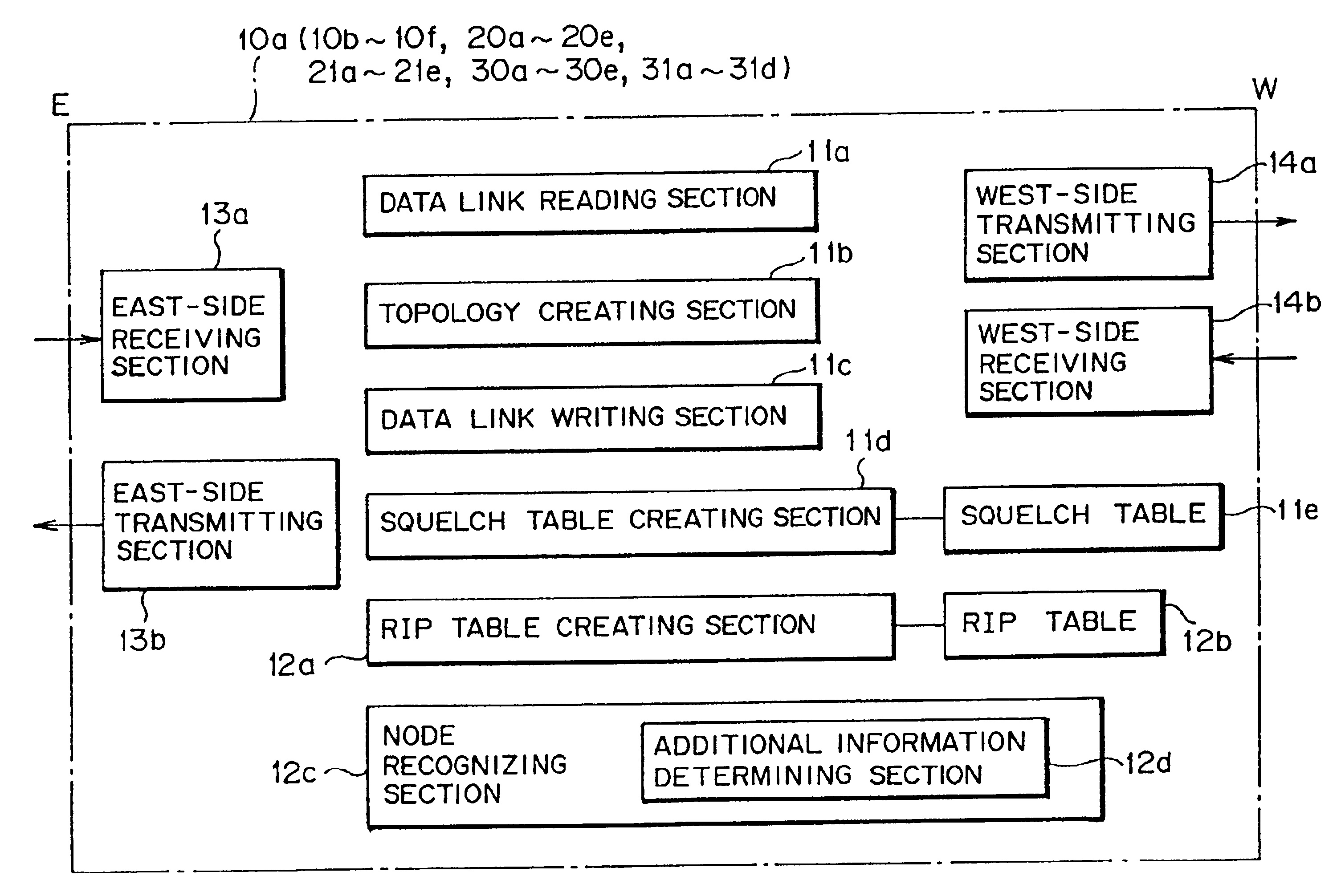
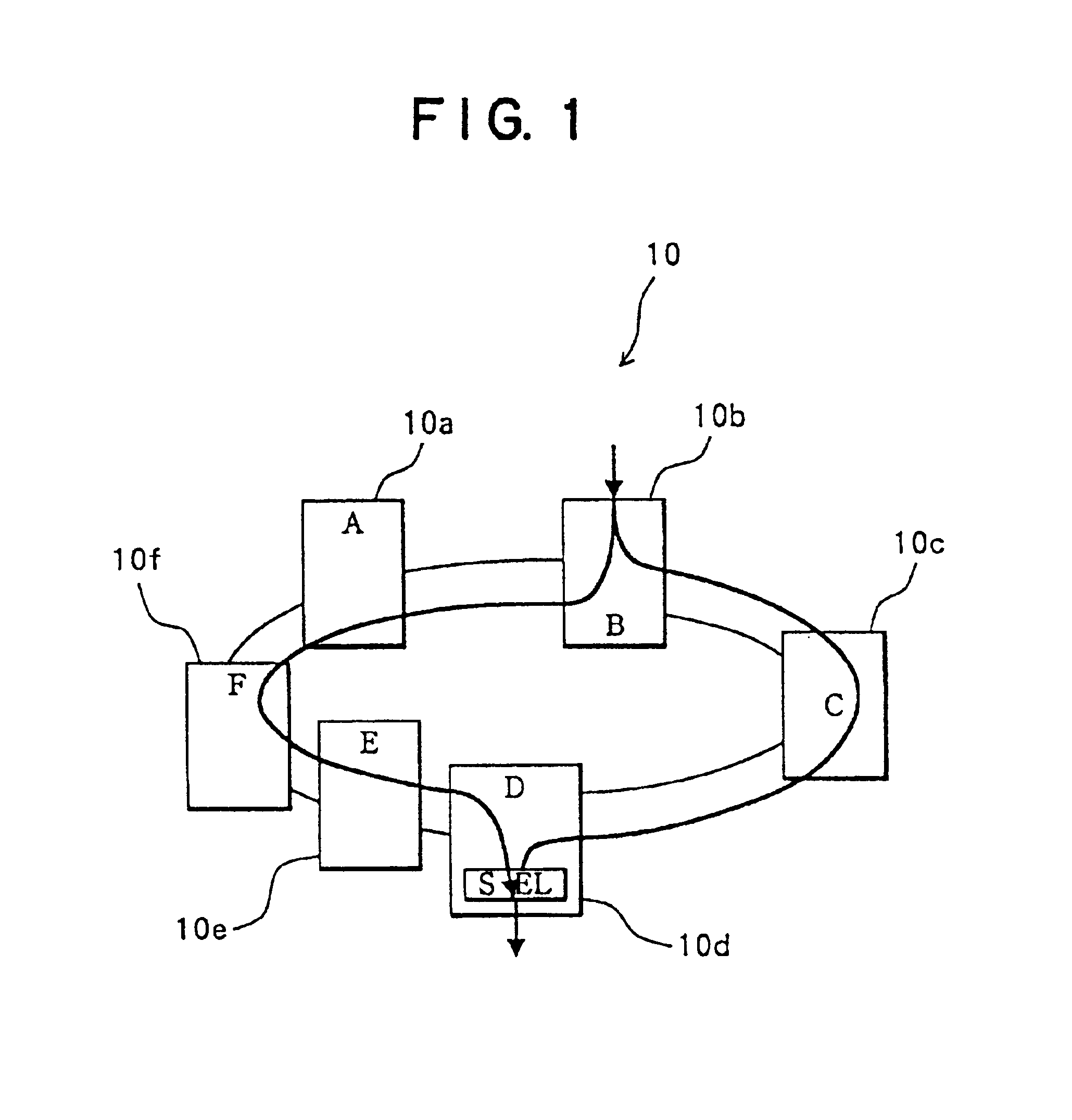
[0266]FIG. 1 is a schematic diagram of a ring transmission system according to a first embodiment of this invention. A ring transmission system 10 shown in FIG. 1 is configured with six optical transmitting apparatuses for a ring transmission system (hereinafter referred to merely as optical transmitting apparatuses, occasionally) 10a, 10b, 10c, 10d, 10e, and 10f connected to one another over a transmission path having a data link channel (data link) in which crossconnect information representing an add node identifier (add node ID) indicating a node to which an optical signal is added, and a drop node identifier (drop node ID) indicating a node from which the optical signal is dropped is written. The transmission path is an optical fiber, over which an optical signal is transmitted through the optical transmitting apparatuses 10a, 10b, 10c, 10d, 10e, and 10f over the optical fiber, and the optical transmitting apparatuses 10a, 10b, 10c, 10d, 10...

second embodiment

[0429](B) Description of the Invention

[0430]SONET system is standardized as one of so-called new synchronous networks in the North America, as stated above. An example of this network, 16 nodes (that are optical transmitting apparatuses referred to as stations, occasionally) are connected in ring to configure a transmission ring.

[0431]The transmission ring is classified into two-fiber BLSR in which nodes are connected by two optical fibers, and four-fiber-BLSR in which nodes are connected by four optical fibers. A bidirectional ring transmission path is formed with a pair or pairs of optical fibers. In the four-fiber BLSR, with two optical fibers as a pair, optical signals are transmitted clockwise over one pair of the optical fibers, while optical signals are transmitted counterclockwise over the other pair, similarly to the two-fiber BLSR.

[0432]In the transmission ring, 16 nodes, for example, are connected to one another over the bidirectional ring transmission path, optical signa...


PUM


Abstract

An optical transmission technique for a ring transmission system that can transmit time-division-multiplexed optical signals in dual directions. An optical transmitting apparatus comprises a data link reading section, a topology creating section, a data link writing section, a squelch table creating section, a squelch table, an RIP table creating section, an RIP table, a node recognizing section, an east-side receiving unit, an east-side transmitting unit, a west-side transmitting unit, and a west-side receiving unit. When a transmission route is switched at plural positions, the squelch table and the RIP table are automatically created as soon as a crossconnect is set. With minimum setting, the ring transmission system can be normally operated without increasing the number of setting items, the squelch table can be created at a high speed using existing hardware, and an alarm can be automatically transmitted from a secondary node until each table is created.

Description

BACKGROUND OF THE INVENTION[0001](1) Field of the Invention[0002]The present invention relates to an optical transmitting apparatus and an optical transmitting method for a ring transmission system suitable for use in a ring transmission system in which a plurality of optical transmitting apparatuses are connected to one another over a bidirectional ring transmission path having a data link channel.[0003](2) Description of Related Art[0004]In optical transmission using optical fibers, signal multiplexing is done with SDH (Synchronous Digital Hierarchy) in order to improve the reliability of transmission lines, improve services, and make management easy. In concrete, the optical transmission uses architecture called SONET (Synchronous Optical Network). SONET is a high-speed leased line service adopting SDH, where a plurality of optical transmitting apparatuses are connected to one another through optical fibers to configure a transmission path in a ring form (hereinafter referred to ...

Claims


Application Information

Patent Timeline
Patent Type & Authority Patents(United States)
IPC IPC(8): H04J3/08H04Q11/04H04B10/032H04B10/07H04B10/27H04B10/275H04B10/291H04L12/42H04L12/43H04L12/437
CPCH04J3/085H04J2203/006H04J2203/0042
Inventor MORIYAMA, JUNICHICHIKAZAWA, TSUTOMUIKEDA, YOSHIHISAYASUI, TAKANORITANIGUCHI, ATSUKISHIODA, MASAHIRO
Owner FUJITSU LTD
Why Eureka
Try Eureka