Cleaning device and image forming apparatus using the same

a cleaning device and image forming technology, applied in the field of copying, printing, facsimile apparatus or similar electrophotographic image forming apparatus, can solve the problems of deterioration of the blade, affecting the cleaning effect, and reducing the amount of residues to reach the cleaning device, so as to preserve the expected cleaning efficiency against aging and simple configuration

Inactive Publication Date: 2005-05-17
RICOH KK
View PDF38 Cites 15 Cited by
  • Summary
  • Abstract
  • Description
  • Claims
  • Application Information

AI Technical Summary

Benefits of technology

[0015]It is an object of the present invention to provide a cleaning device capable of preserving expected cleaning efficiency against aging with a simple configuration, and an image forming apparatus using the same.

Problems solved by technology

When the brush is constantly held in contact with the photoconductive element, the following problems arise, depending on the amount of residues left on the photoconductive element.
However, when the amount of image formation effected on the photoconductive element, i.e., when an image with a small area ratio is repeatedly formed on the photoconductive element, the amount of residues to reach the cleaning device decreases little by little.
As a result, heavy load acts on the blade, which is used in combination with the brush, and accelerates the deterioration of the blade, thereby rendering cleaning defective.
In addition, maintenance cost increases due to frequent replacement of the cleaning member.
However, when the surface of the photoconductive element is ground, it is likely that the abrasive and part of a photoconductive layer shaved off are introduced in a developer.
This not only lowers image quality, bur varies chargeability due to the variation of the thickness of the photoconductive layer and scratches the surface of the photoconductive layer.
This, however, brings about another problem that when the photoconductive element is in a halt, the residues between the photoconductive element and the rubber roller remain pressed against the photoconductive element and are therefore positively deposited on the photoconductive element.
However, when frictional resistance is reduced, the cleaning member is apt to fail to remove discharge products different from the residues described above.
The nitric compound, which is moisture-absorptive, has high resistance in a low humidity environment, but has low resistance in a high humidity environment due to moisture absorption.
This obstructs the deposition of toner on the image portion and is likely to bring about the local omission of an image.
However, the brush used to clean the photoconductive element brings about the problems stated earlier, depending on the amount of residues collected from the photoconductive element.

Method used


Image

  • Cleaning device and image forming apparatus using the same
  • Cleaning device and image forming apparatus using the same
  • Cleaning device and image forming apparatus using the same

Examples


Embodiment Construction

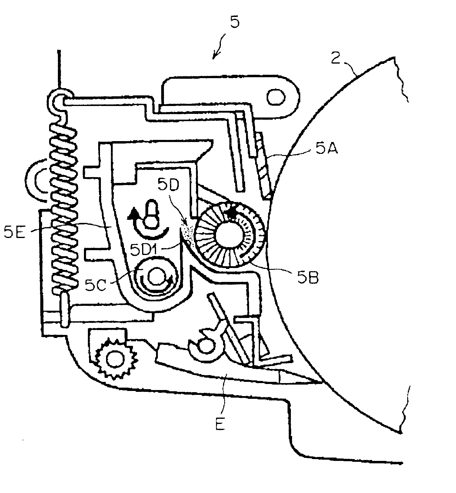
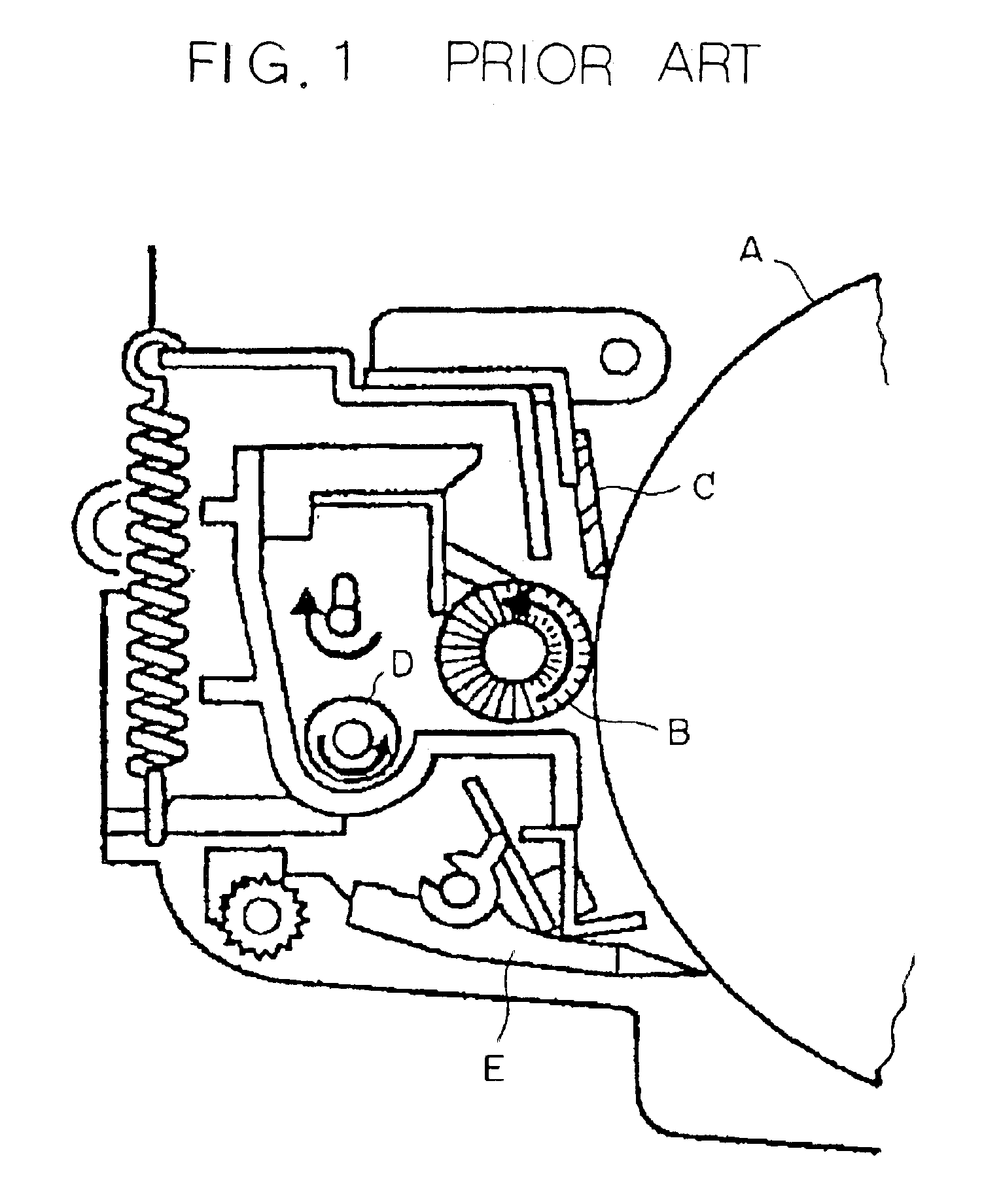
[0036]To better understand the present invention, brief reference will be made to a conventional cleaning device for an image forming apparatus, shown in FIG. 1. As shown, the cleaning device includes a brush B and a blade C held in contact with the circumference of a photoconductive element or image carrier A. The photoconductive element A is implemented as a drum. A coil D is positioned behind the brush B in order to convey collected toner for a recycling purpose. Labeled E in FIG. 1 is a peeler for peeling off a sheet or recording medium from the drum A. The problem with the brush B is that it has looped tips and therefore brings about defective cleaning, as discussed earlier.

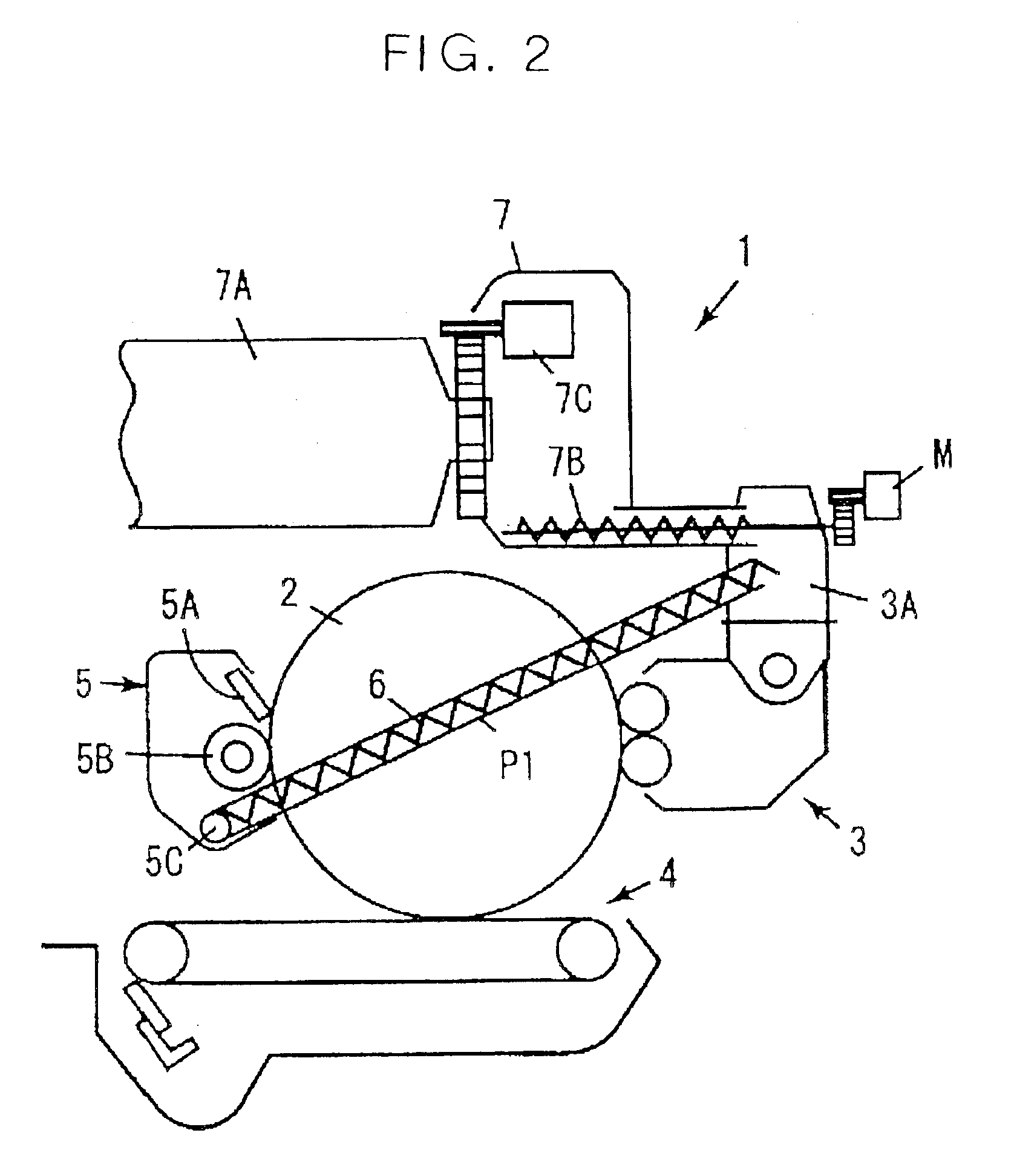
[0037]Referring to FIG. 2, an image forming apparatus including a cleaning device embodying the present invention is shown. While the image forming apparatus is implemented as a copier in FIG. 2, the illustrative embodiment is applicable to any other image forming apparatus, e.g., a printer or a facsimile ap...


PUM


Abstract

A cleaning device for cleaning an image carrier by removing toner and other residues left thereon of the present invention includes a brush having tips, which contact the surface of the image carrier, provided with a loop configuration and a contact pressure of 50 g/cm2. A toner collecting space is located at a position adjacent to the brush and at which the tips of the brush contacted the surface of the image carrier arrive in accordance with the movement of the brush.

Description

BACKGROUND OF THE INVENTION[0001]1. Field of the Invention[0002]The present invention relates to a copier, printer, facsimile apparatus or similar electrophotographic image forming apparatus and more particularly to a cleaning device included in an image forming apparatus for removing various residues, including toner contained in a developer, paper dust and additives contained in toner and a sheet, left on a photoconductive element or similar image carrier after image transfer.[0003]2. Description of the Background Art[0004]Generally, an electrophotographic image forming apparatus includes a photoconductive element, which is a specific form of an image carrier. A charging step and an image writing step are sequentially executed with the photoconductive element to form a latent image thereon. Subsequently, the latent image is developed by a developing step using toner to become a toner image. The toner image is transferred to a sheet or recording medium by an image transferring step...

Claims


Application Information

Patent Timeline
Patent Type & Authority Patents(United States)
IPC IPC(8): G03G21/00
CPCG03G21/0035
Inventor KAWAHARA, SHINICHITAKANO, SATOSHISAITOH, HIROSHISUGIYAMA, TOSHIHIROISHII, HIROKAZUARAI, YUJI
Owner RICOH KK
Why Eureka
Try Eureka