Workpiece coordinate system origin setting method, workpiece coordinate system origin setting program and workpiece coordinate system origin setting device of a surface property measuring machine

a technology of workpiece coordinate system and origin setting, which is applied in the direction of mechanical measurement arrangement, mechanical roughness/irregularity measurement, instruments, etc., can solve the problems of methods not being used to set origin, difficult to obtain data of the surface of a workpiece in the direction perpendicular to the shaking direction, and difficult to detect directly a portion having a feature in its shape. achieve the effect of executing the origin setting at a low cost and quickly, and facilitating the preparation of the measuremen

Active Publication Date: 2005-05-17
MITUTOYO CORP
View PDF7 Cites 10 Cited by
  • Summary
  • Abstract
  • Description
  • Claims
  • Application Information

AI Technical Summary

Benefits of technology

[0038]The present invention was conceived in view of the above conventional tasks. The object of the invention is to provide a method, a program and a device that can set accurately and easily the origin of a coordinate system of a workpiece based on the result obtained by scanning over a feature area on the surface of the workpiece.

Problems solved by technology

Now, since a detector having such a structure is a one (1)-axis detector detecting the unevenness in the direction of its shaking (Z-axis direction being the vertical direction for a detector of a surface roughness tester and a contour measuring machine and, X-axis direction being the direction to back and forth for a detector of a roundness measuring machine), the data of the surface of a workpiece in the direction perpendicular to the shaking direction are difficult to obtain.
For example, it is difficult to detect directly a portion having a feature in its shape such as an edge of a workpiece (that is a corner portion of the workpiece and often forms an angle of 90° in general).
However, those methods are not for setting the origin.
However, a calculation process accompanied by a complicated analysis is necessary for the data in order to estimate feature points such as an edge portion of a workpiece and to set a feature point correctly as the origin of the workpiece coordinate system.
Thus, conventionally, much time is necessary for the calculation process.
Thus, conventionally, much time is necessary for the process.
Furthermore, since there are cases where a workpiece itself is very small, it is very difficult to determine at which point of the workpiece the origin should be set because visual confirmation is difficult.
However, conventionally, much time is necessary for measurement and much time is also necessary for the form analysis process.
When the shape of the feature area is complicated, it may be approximated to a simple shape and sufficient accuracy can not be obtained in that case.
Furthermore, very sufficient accuracy can not be obtained even when a complicated form analysis has been executed.

Method used


Image

  • Workpiece coordinate system origin setting method, workpiece coordinate system origin setting program and workpiece coordinate system origin setting device of a surface property measuring machine
  • Workpiece coordinate system origin setting method, workpiece coordinate system origin setting program and workpiece coordinate system origin setting device of a surface property measuring machine
  • Workpiece coordinate system origin setting method, workpiece coordinate system origin setting program and workpiece coordinate system origin setting device of a surface property measuring machine

Examples


first embodiment

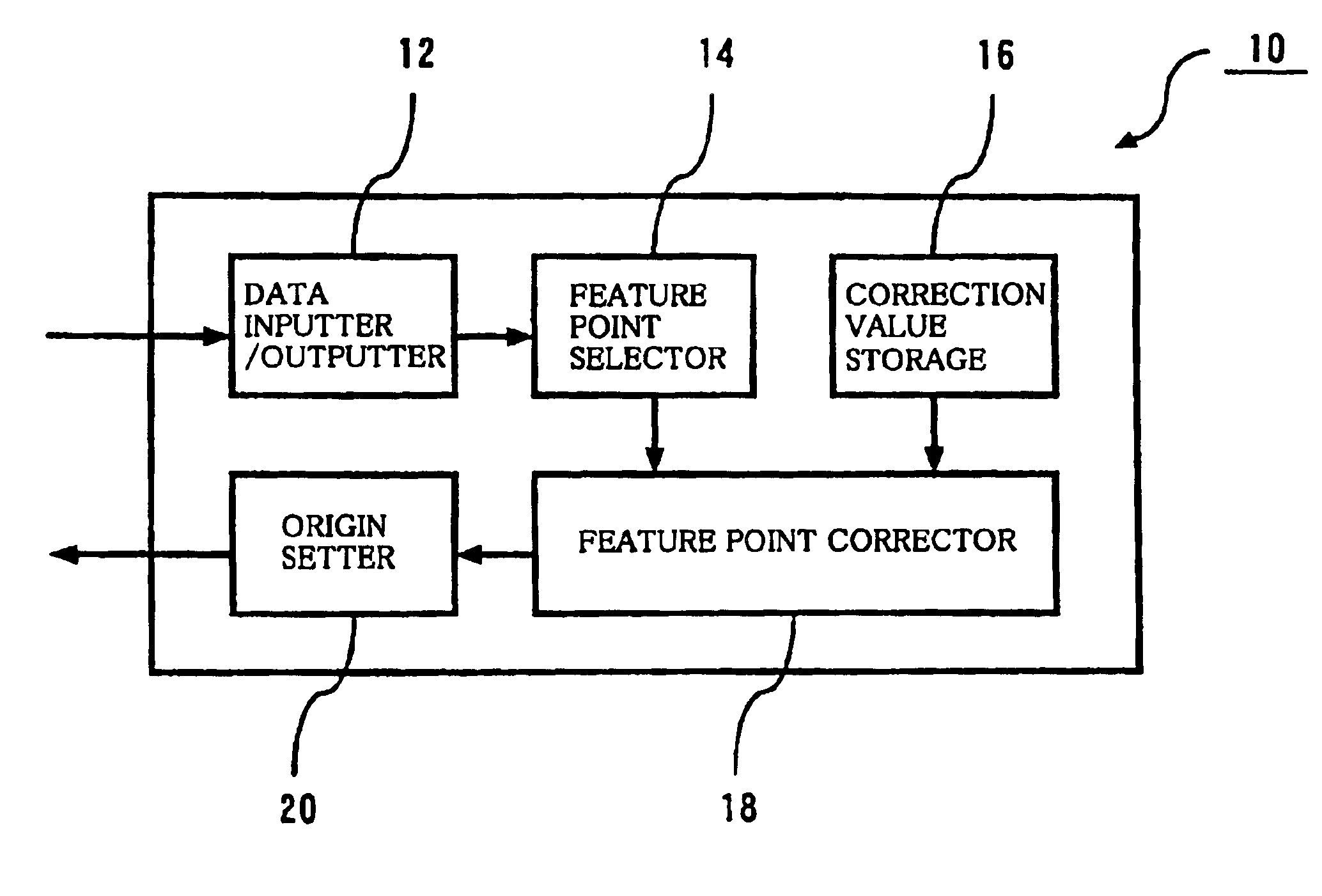
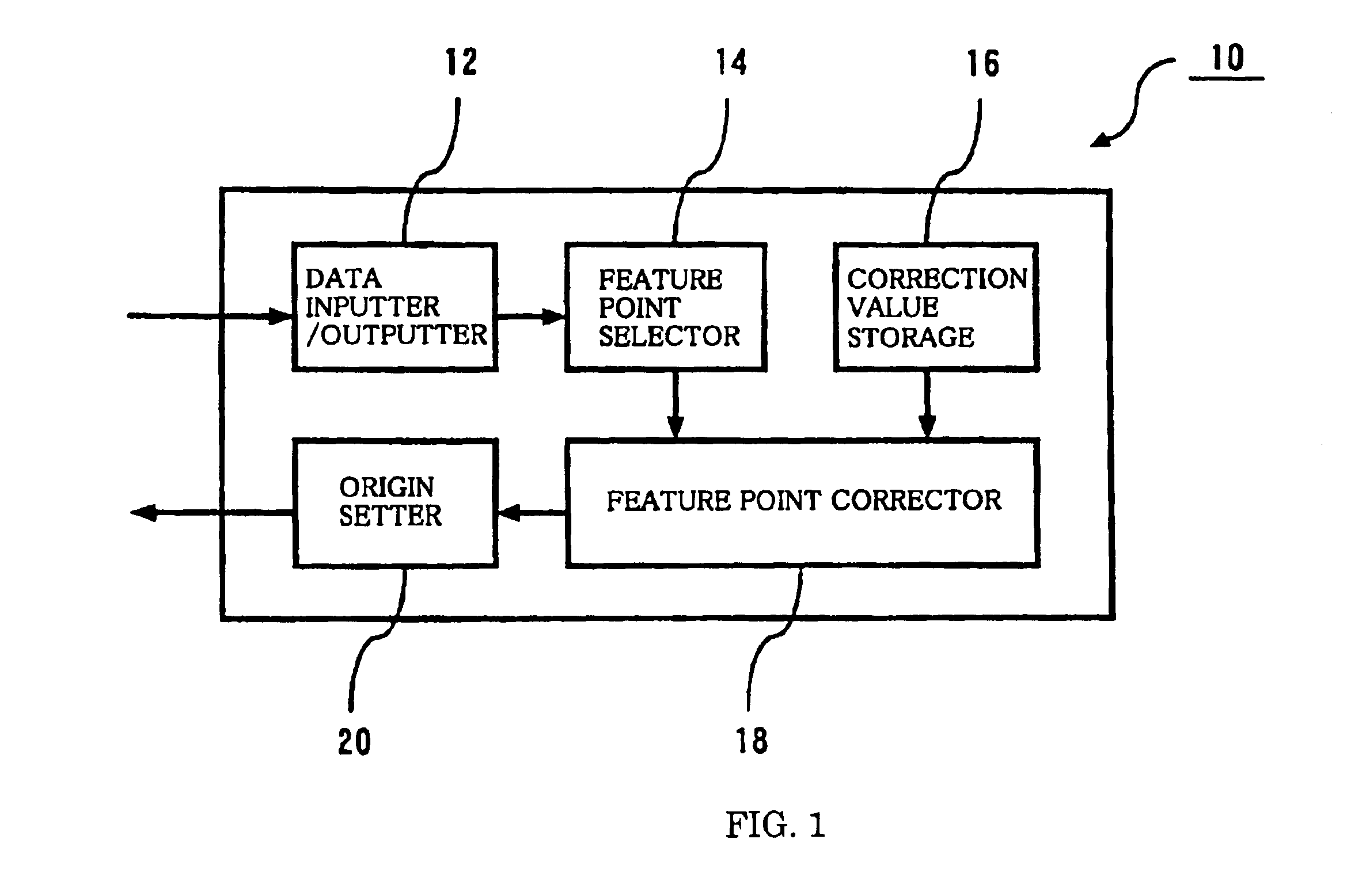
[0124]FIG. 1 shows a schematic structure of an origin setting device of a surface texture measuring machine according to the invention.

[0125]The origin setting device 10 of the surface texture measuring machine shown in FIG. 1 comprises, for example, a computer and includes a data inputter / outputter (inputter) 12, a feature point selector 14, a correction value storage 16, a feature point corrector 18 and an origin setter 20.

[0126]The origin setting device 10 may be structured as an independent machine and may be combined with a conventional surface texture measuring machine. Furthermore, the origin setting device 10 may be built-in type and may be integrated in a surface texture measuring machine. In either case, the data inputter / outputter 12 inputs the data in the detection-axis direction (Z-axis data) detected by a stylus and scanning position data in the workpiece surface direction (driving-axis direction) (X-axis data) when the stylus of a surface texture measuring machine is ...

second embodiment

[0192]Next, FIGS. 4 show flowcharts of the feature point selection step. FIG. 4 (A) shows the case where feature points of the data are determined based on the maximum or the minimum of the data and FIG. 3 (B) shows the case where feature points of the data are determined based on the rate of variation of inclination angles of the minute ranges of the data.

The Maximum and the Minimum

[0193]First, the process is started with Step 711 (S711).

[0194]As shown in FIG. 4 (A), when the feature points of the feature area data are determined based on the maximum or the minimum of the feature area data, the points at which the Z-axis data of the feature area data becomes the maximum or the minimum are calculated in a maximum / minimum calculation step (S712).

[0195]Following the maximum / minimum calculation step (S712), feature points are extracted and determined in a feature point determination / selection step (S714).

[0196]That is, in the feature point determination / selection step (S714), the point...


PUM


Abstract

The object of the invention is to provide a method, a program and a device that can set accurately and easily the origin of the coordinate system of a workpiece based on the result obtained by a surface texture measuring machine scanning over a feature area on the surface of the workpiece. The device comprises a data inputter for inputting data obtained by scanning a feature area including at least a feature point area and a non-feature point area of the surface of a workpiece, a feature point selector for extracting the feature points of the data by statistically processing the data inputted into the data inputter and an origin setter for setting the origin of a workpiece coordinate system relative to an origin setting target point of the workpiece based on the coordinate values of the feature point obtained by the feature point selector.

Description

RELATED APPLICATIONS[0001]This application claims priority to the Japanese Patent Application 2002-340930 dated on Nov. 25, 2002 and is hereby incorporated with reference for all purposes.BACKGROUND OF THE INVENTION[0002]1. Technical Field[0003]The present invention relates generally to setting of the origin of a surface texture measuring machine represented by a roundness measuring machine, a surface roughness tester, a contour measuring machine and a three (3)-dimensional coordinate measuring machine and, more specifically, to a method, a program and a device for workpiece coordinate system origin setting.[0004]2. Background Art[0005]A detector used in a surface texture measuring machine such as a roundness measuring machine, a surface roughness tester and a contour measuring machine and having a structure in which a stylus is provided at the tip of a lever capable of shaking freely in a direction perpendicular to the surface of a workpiece is widely used. In a state where the sty...

Claims


Application Information

Patent Timeline
Patent Type & Authority Patents(United States)
IPC IPC(8): G01B21/02G01B21/04G01B5/28G01B5/008G01B5/012G01B11/03
CPCG01B5/012G01B21/045G01B5/28
Inventor SAKURADA, JUNJIKOJIMA, TSUKASATAMAI, TOSHIYUKI
Owner MITUTOYO CORP
Why Eureka
Try Eureka