Humidity sensor

a technology of humidity sensor and sensor, which is applied in the direction of heating types, instruments, specific gravity measurement, etc., can solve the problems of sensor failure or misreading, lack of sensor accuracy at high relative humidity, and possibility of liquid condensate flowing onto the sensor

Inactive Publication Date: 2005-05-24
FISHER & PAYKEL HEALTHCARE LTD
View PDF5 Cites 99 Cited by
  • Summary
  • Abstract
  • Description
  • Claims
  • Application Information

AI Technical Summary

Benefits of technology

[0007]It is therefore an object of the present invention to provide a heated humidity sensor which goes some way to overcoming the abovementioned disadvantages in the prior art or which will at least provide the industry with a useful choice.
[0013]and a second disinfection mode configured to provide a second said energisation power to said heater to heat said humidity transducer to a predetermined disinfection temperature, said disinfection temperate being higher than said operating temperature and adequate to substantially kill the majority of any common pathogens present on said humidity transducer.
[0037]a humidity sensor adapted to be located in said interior providing an estimate of the absolute humidity of said flow of gases, in use said humidity sensor juxtapositioned below said protrusion, said protrusion thereby substantially preventing any liquid water from flowing down said conduit onto said humidity sensor.
[0044]heating said humidity transducer to a predetermined disinfection temperate, said disinfection temperature being adequate to substantially kill the majority of any common pathogens present on said humidity transducer.
[0062]positioning a humidity sensor below said protrusion, said protrusion thereby substantially preventing any liquid water from flowing down said interior onto said humidity sensor, and

Problems solved by technology

Problems associated with such gas streams include lack of sensor accuracy at high relative humidity and the possibility of liquid condensate flowing onto the sensor.
A further disadvantage of measurement in high dewpoint gases is the possibility of sensor failure or misreading.
This introduces design constraints such as small size, robustness and ability to be sterilised to prevent cross-contamination between patients.
This means that certain key humidity parameters, such as average absolute humidity during the inspiratory part of the flow cycle, are unable to be measured.

Method used


Image

  • Humidity sensor
  • Humidity sensor
  • Humidity sensor

Examples


Embodiment Construction

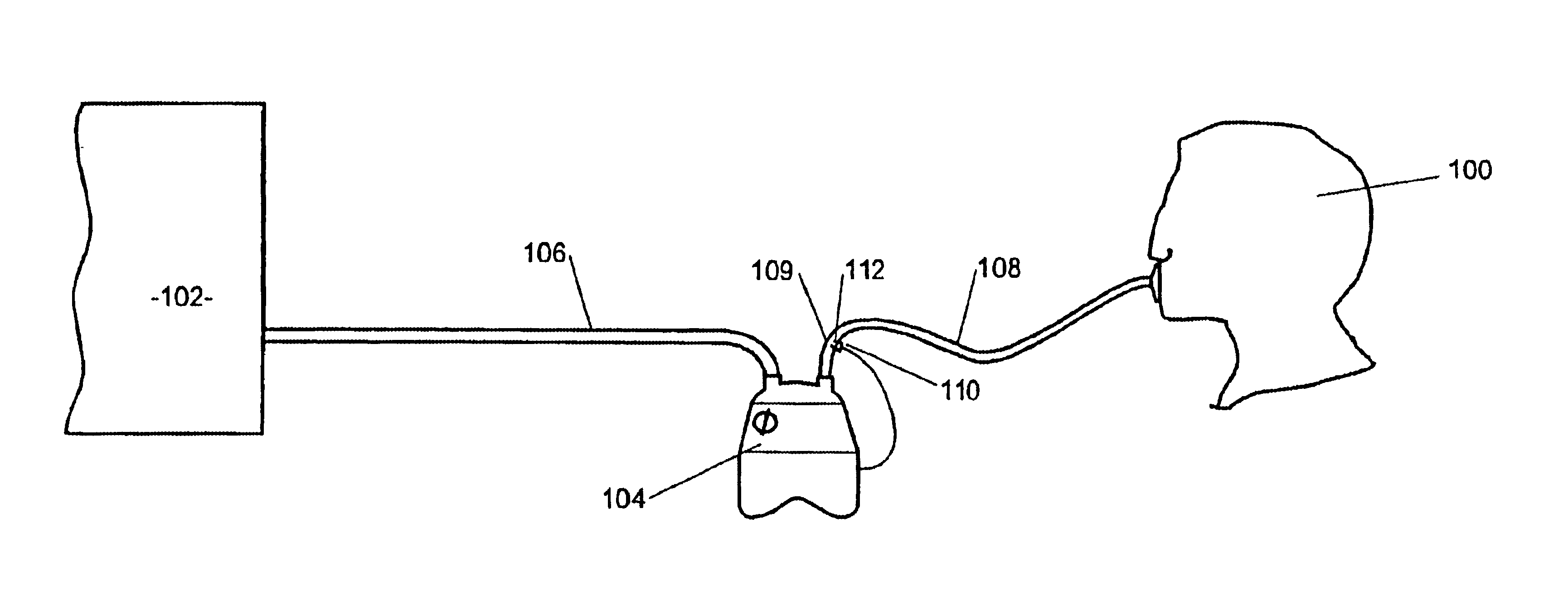
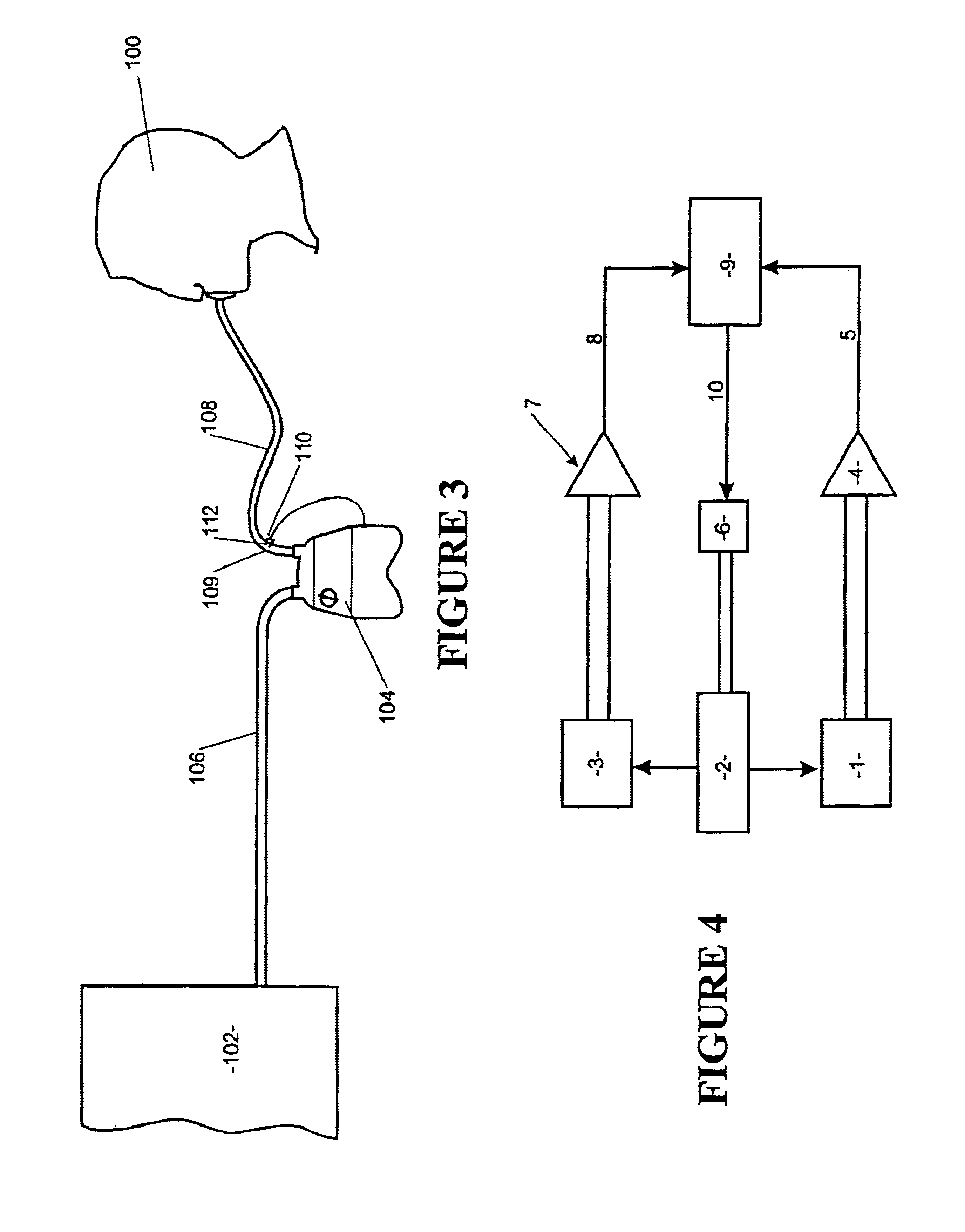
[0071]The present invention relates to a humidity sensor which is designed:[0072]1. To operate in high dewpoint situations where the relative humidity may be high, and liquid water may be present.[0073]2. To detect sensor misreading or failure.[0074]3. To be strong, robust and capable of sterilisation.[0075]4. When flow is rapidly changing in a cyclic manner, to detect key parameters of the instantaneous absolute humidity waveform by mathematically combining the reading from the humidity sensor with knowledge of the gas flow waveform.

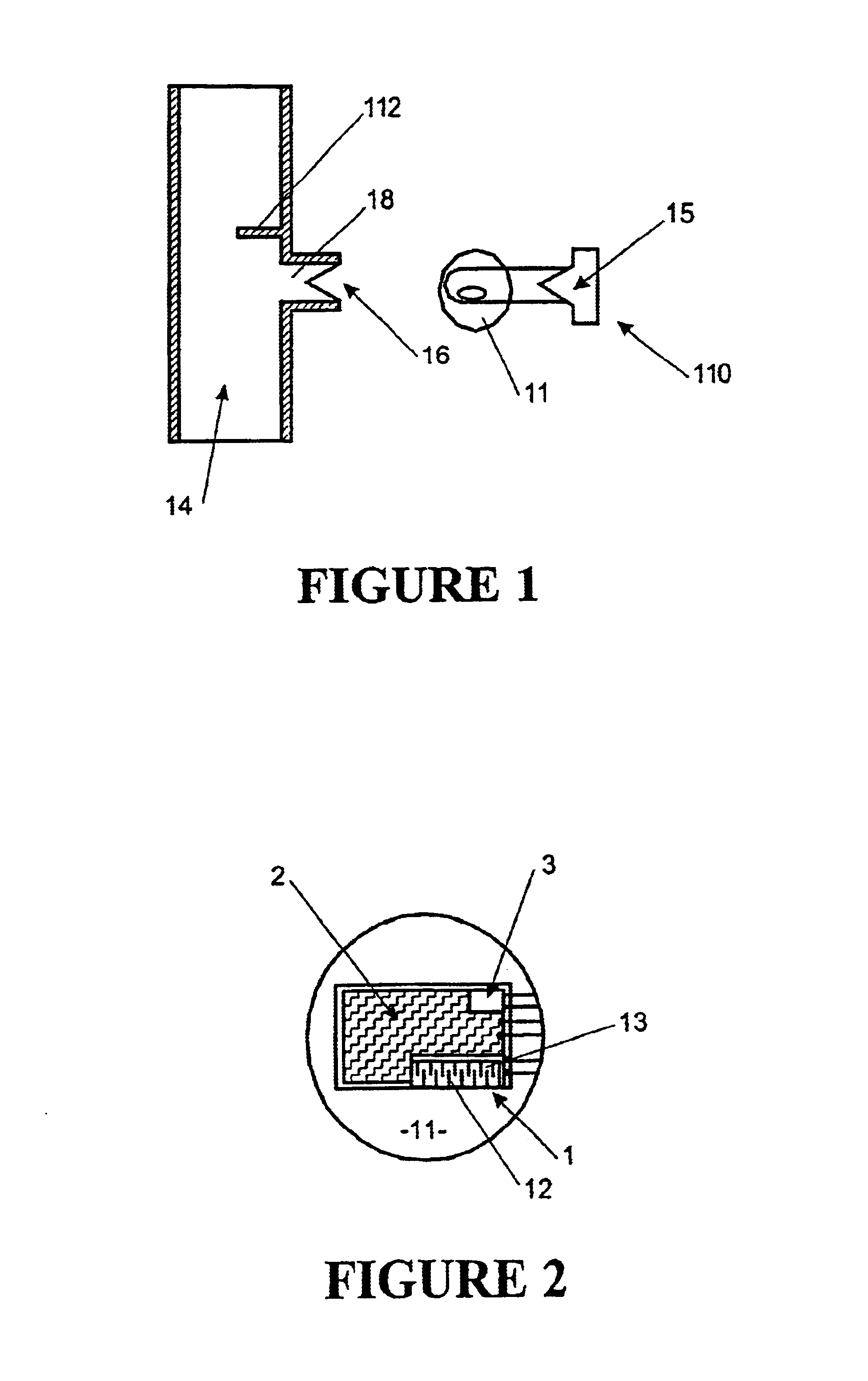
[0076]Polymer absorption sensors are well known in the prior art and consist of two parts: a water-vapour porous polymer matrix, and a set of electrical sensing electrodes. The amount of water vapour which is absorbed into the polymer matrix is determined by the relative humidity of the gas in close contact with the polymer matrix. The electrodes allow the measurement of electrical properties related to the amount of water vapour in the polymer matrix. ...


PUM

PropertyMeasurementUnit
temperatureaaaaaaaaaa
absolute humidityaaaaaaaaaa
relative humidityaaaaaaaaaa

Abstract

A method and apparatus are described for sensing the absolute humidity of gases where the relative humidity of gases are measured, the humidity transducer is heated, the resulting temperature measured and the absolute humidity calculated (based on the power to heat said transducer, the temperature of said transducer and the relative humidity).In further embodiments the humidity transducer may be heated to a pasteurisation temperature, to substantially kill any common pathogens present on the humidity transducer. The flow rate may be determined to estimate a more instantaneous valve of humidity. The operation of the sensor may be continually monitored for correct operation and various constructions disclosed for improving the efficiency of operation.

Description

FIELD OF THE INVENTION[0001]The present invention relates to the use of heated humidity sensors particularly though not solely to the use of heated humidity sensors with respiratory humidifiers for assisted patient breathing.BACKGROUND OF THE INVENTION[0002]Heated humidity sensors are hereby described that allow the measurement of humidity in gases having a dewpoint above the temperature of the surrounding environment. Problems associated with such gas streams include lack of sensor accuracy at high relative humidity and the possibility of liquid condensate flowing onto the sensor. A further disadvantage of measurement in high dewpoint gases is the possibility of sensor failure or misreading.[0003]Such humidity sensors could be used, for example, as part of a humidity-controlled medical humidifier. This introduces design constraints such as small size, robustness and ability to be sterilised to prevent cross-contamination between patients.[0004]When a medical humidifier is used with...

Claims


Application Information

Patent Timeline
Patent Type & Authority Patents(United States)
IPC IPC(8): G01N25/56G01N27/22G01N27/12A61L2/04A61M16/16F24F6/00G01N27/02G01N27/04
CPCG01N27/223G01N27/121A61M16/161A61M2205/3368A61M2016/0039A61M16/16A61M2205/3653A61M16/0066
Inventor SEAKINS, PAUL JOHNSMITH, MALCOLM DAVIDABEYSINGHE, KAUMALI PRASANGIKA
Owner FISHER & PAYKEL HEALTHCARE LTD
Why Eureka
Try Eureka