Acoustic micro imaging method and apparatus for capturing 4D acoustic reflection virtual samples

a micro-imager and virtual sample technology, applied in the direction of mechanical roughness/irregularity measurement, instruments, specific gravity measurement, etc., can solve the problems of not being able to derive additional information from the stored x-y-z data set of amplitude peak values, and the potential value of ripple information is lost forever

Inactive Publication Date: 2005-05-24
NORDSON CORP
View PDF15 Cites 36 Cited by
  • Summary
  • Abstract
  • Description
  • Claims
  • Application Information

AI Technical Summary

Benefits of technology

[0044]Another significant object of the present invention is to capture dramatically greater data than in any prior method, making possible a more accurate and comprehensive understanding of the internal acoustic impedance structure within an examined sample.

Problems solved by technology

Using conventional C-Mode AMI, the potentially valuable information contained in those ripples is lost forever.
However, many applications exist wherein the information desired to be retrieved from the solid part is not precisely known at the time the part is acoustically interrogated.
Since the acoustic reflectance signals returned from each pulse are lost, except for the peak of the signal within the gated region (and optionally, polarity and TOF data), it is not possible to derive additional information from the stored X-Y-Z data set of amplitude peak values.
It is not possible off-line, for example, to adjust the position of the gate to change the depth of the inspected plane.
Nor is it possible to employ signal processing analytics on the missing acoustic signal information to learn more about the anomalies which perturbed the insonifying sound pulses.
One obvious and significant disadvantage of this approach, however, is that all images generated by changing gate position are not in sharp focus.
As will become evident from the ensuing description, another drawback of moment of this last-described approach is the limited amount of data that can be gathered in a single scan of the sample.

Method used


Image

  • Acoustic micro imaging method and apparatus for capturing 4D acoustic reflection virtual samples
  • Acoustic micro imaging method and apparatus for capturing 4D acoustic reflection virtual samples
  • Acoustic micro imaging method and apparatus for capturing 4D acoustic reflection virtual samples

Examples


example 1

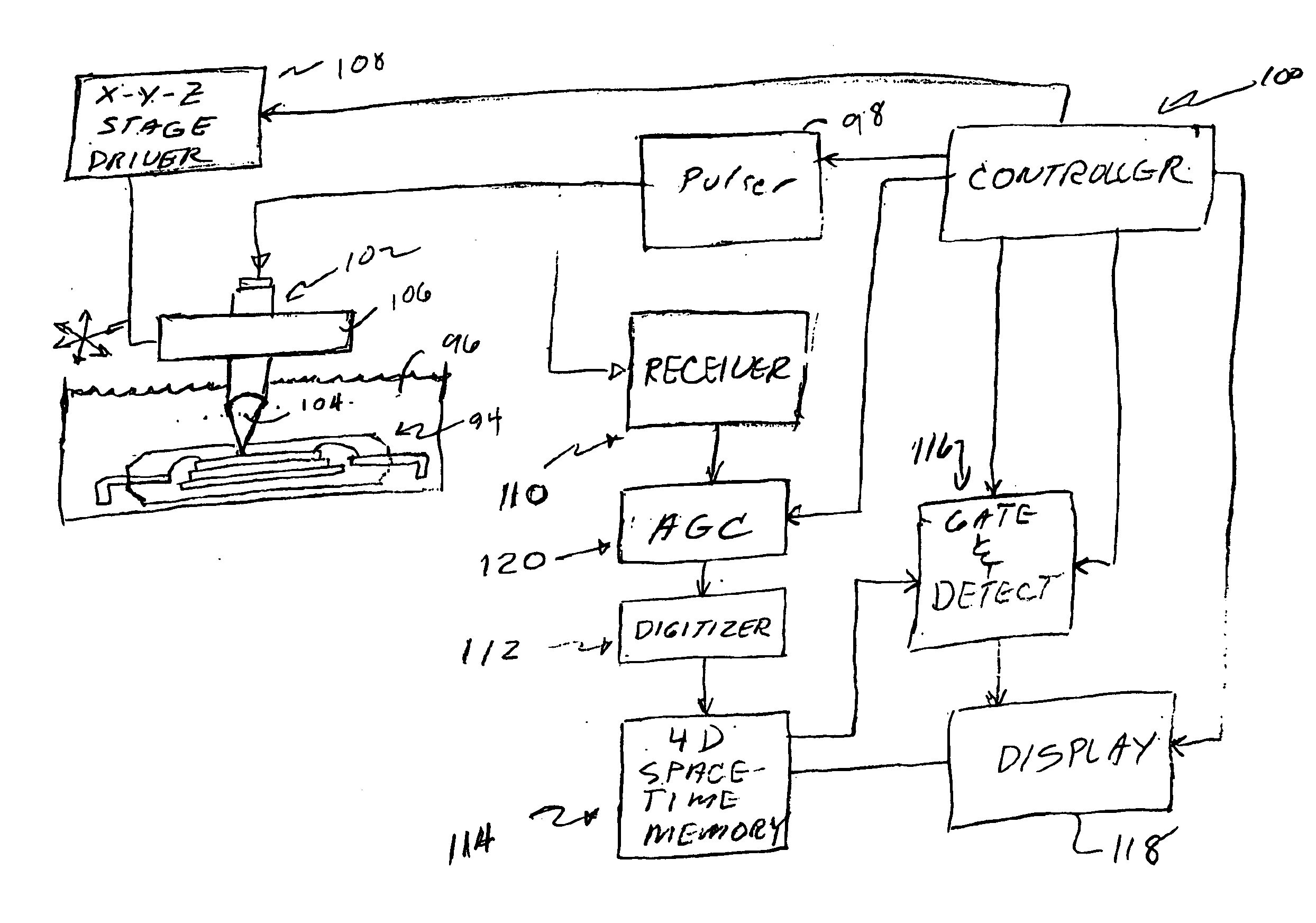
[0142]For one unique set of points in 4-space, which correlates to a unique position of the transducer (X1, Y1, Z1), there will be the 4000 values, one for each of the A-scan points captured at that position. If the capture gate is set as indicated for this sample, then there will be A-scan values that are equally spaced in time and that start before the top surface of the sample and that end after the bottom surface of the sample.

example 2

[0143]For another unique set of points in 4-space (X3, Y4, and T=‘150 samples later than the sample point that correlates to the sample surface’,) there will be 10 different values, one for each of the 10 different Z positions of the transducer used for the ten different slices.

example 3

[0144]For a third unique set of points in 4-space (Y19, Z6, and T=‘112 samples later than the sample point that correlates to the sample surface’,) there will be 256 different values, one for each of the 256 different X positions of the transducer at which data were captured.

[0145]The resulting virtual sample will thus be captured in a full 4D data set which can be processed and displayed as though the live sample were present. Having the virtual sample may in some respects be an advantage over operations in real time, as processing speeds need not be so rapid when analyzing a virtual sample off line.

[0146]Whereas the FIGS. 20-23 method is described in the context of successive X-Y raster scans along the Z axis, in a more general sense the invention concerns taking a succession of scans with a probe at three-dimensionally varied locations in a sample or sample portion as the probe is moved in the direction of the probe axis. The location of the depth of field of the probe is adjuste...


PUM

PropertyMeasurementUnit
frequenciesaaaaaaaaaa
focal lengthaaaaaaaaaa
frequencyaaaaaaaaaa

Abstract

For use in acoustic micro imaging, a method (and implementing apparatus) is disclosed for creating a 4D virtual sample data memory. The method comprises employing a pulsed ultrasonic microscope probe to interrogate a sample at three-dimensionally varied locations in the sample. Data developed by the microscope probe includes for each location interrogated a digitized A-scan for that location. The developed data is stored in a data memory.

Description

BACKGROUND OF THE INVENTION[0001]This invention concerns improvements in the field of non-destructive testing and failure analysis using pulsed ultrasound as a material probe. While many of the applications of the invention are useful in a broad range of applications, the invention will be described in the context of acoustic micro imaging (“AMI”). To further an understanding of the broad applicability of the principles of the invention, a brief description will be engaged of various scanning modes commonly employed today in AMI.[0002]The most basic form of acoustic interrogation is illustrated in FIG. 1 in which an ultrasonic transducer 20 is excited with a sharp electrical pulse and emits a pulse of ultrasonic energy which is brought to a focus 22 within sample 24 by a lens (not shown) at the distal end of the transducer 20. FIG. 1A is intended to represent the sample 24 as having a front surface A, an internal interface (acoustic impedance mismatch), and a bottom surface C. An ac...

Claims


Application Information

Patent Timeline
Patent Type & Authority Patents(United States)
IPC IPC(8): G01N29/38G01N29/06G01N29/36G01S15/89G01S15/00
CPCG01N29/0609G01N29/0681G01S15/8993G01N29/38G01N2291/015
Inventor ORAVECZ, MICHAEL G.BASTERFIELD, ALAN
Owner NORDSON CORP
Why Eureka
Try Eureka