
Low profile decking beam

a low-profile, beam technology, applied in the direction of load securing, transportation items, loading/unloading vehicle arrangment, etc., can solve the problem that the exposed keepers are subject to being snagged on objects

Inactive Publication Date: 2005-05-24
ANCRA INTERNATIONAL CORPORATON
View PDF9 Cites 24 Cited by
  • Summary
  • Abstract
  • Description
  • Claims
  • Application Information

AI Technical Summary

Benefits of technology

[0007]The device of the invention overcomes the shortcomings of the prior art in providing a keeper which effectively protected against exposure to surrounding objects which might cause it damage.
[0008]The device of the present invention utilizes a beam with an end foot which has a notch formed on its bottom surface and a flat top surface. A keeper is pivotally mounted on the end foot and is spring urged so that its top under surface is driven in abutment against the flat top surface of the end foot. The keeper has tabs on the sides thereof which can be used to manually pull the top of the keeper away from the top surface of the end foot. A slot is formed in a track to which the end foot of the beam is attached. With the notch on the bottom of the end foot fitted into the slot and with the spring released so that the opposing surfaces of the end foot and keeper are in abutment against each other, the keeper and end foot fit snugly within the slot and are maintained in this position by the spring action. When the keeper is manually retracted, the end foot can be removed from the slot. The keeper and the end foot in their installed positions thus have few exposed portions which are likely to be hit against and damaged.

Problems solved by technology

Such prior art keepers protrude above or below the surface of the deck beam where they are subject to being struck by cargo pallets carried on forklifts, loose objects, or other members.
Also, such exposed keepers are subject to being snagged on objects.
Consequently such prior art exposed keepers are likely to be bent or otherwise damaged rendering them non-functional.

Method used


Image

  • Low profile decking beam
  • Low profile decking beam
  • Low profile decking beam

Examples


Embodiment Construction

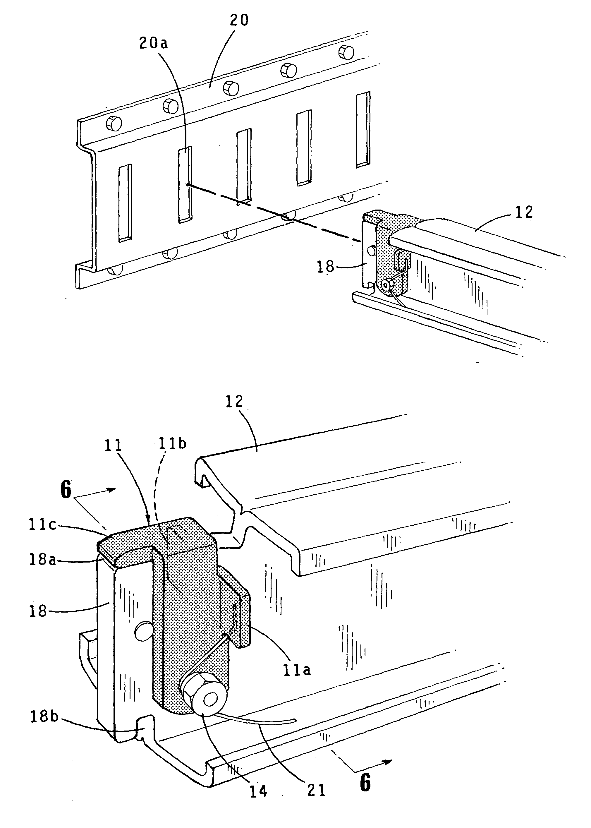
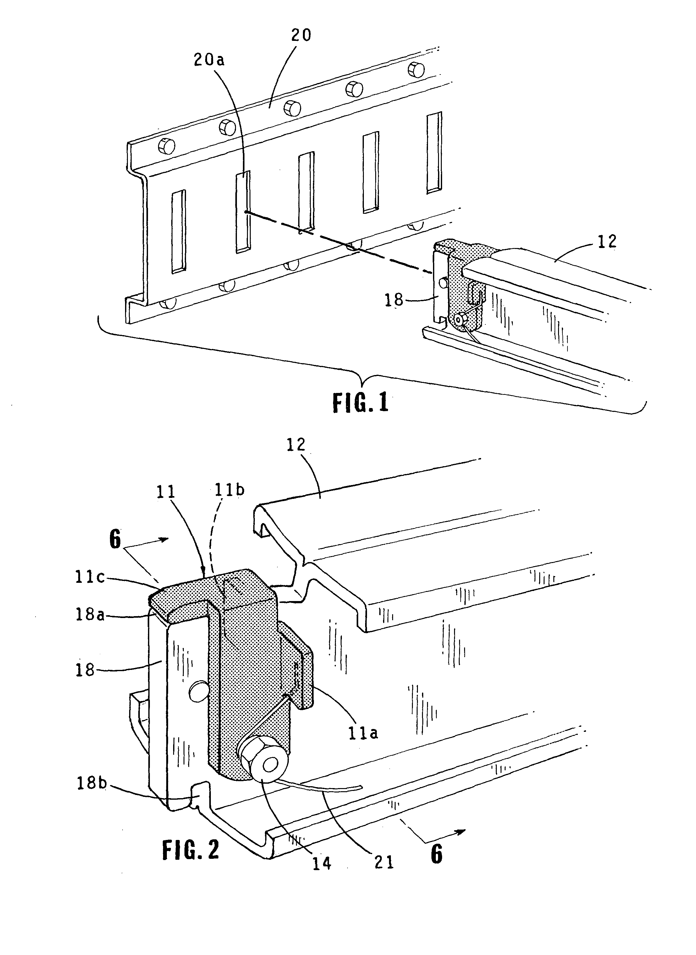
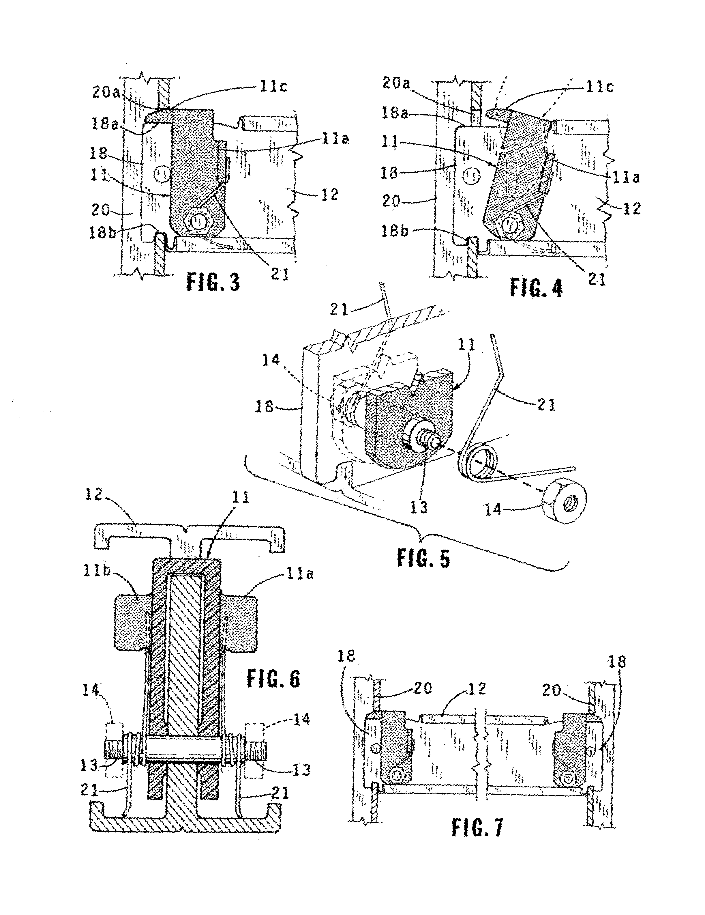
[0016]Referring to the FIGS., beam 12 has an end foot portion 18 on each end which has a notch 18b on the bottom and a flat top portion 18a. A keeper 11 is pivotally mounted on each end foot portion 18 by means of bolt 13 and nut 14. In its installed position, the top extension piece 11c of the keeper abuts against the top edge of slot 20a with notch 18b of the end foot portion 18 fitted over the bottom edge of slot 20a as shown in FIGS. 3 and 7.

[0017]Each keeper has a pair of tabs 11a and 11b extending from its opposite sides. To install or remove the beam from a slot 20a of track 20, tabs 11a and 11b are manually actuated to bring the keeper to the position shown in FIG. 4. This retracts the top piece 11c of the keeper away from the top surface 18a of the end foot 18. As indicated in FIG. 4, the end foot 18 can then is moved upwardly in slot 20a and notch 18b disengaged from the bottom edge of the slot and the end foot removed from the slot.

[0018]The end foot can be installed in a...


PUM


Abstract

A beam for supporting a removable second deck for carrying cargo in a vehicle such as a truck trailer is supported between a pair of opposing tracks on opposite sides of the vehicle. The track has slots formed therein to which the beam is attached. The beam has an end foot on each end. Each foot has a keeper pivotally mounted thereon, the keeper being used to removably attach the foot to the slot. The foot has a notch formed in its bottom surface which engages the bottom edge of the slot. The keeper is spring urged against the foot portion to bring the top portions of the keeper and foot into abutment against each other so that the top of the keeper is in abutment against the top edge of the slot, thereby retaining the foot and keeper in the slot. The foot portion and keeper can be withdrawn from the slot by manually moving the keeper away from the foot against the spring tension.

Description

[0001]This application is based on Provisional Application No. 60 / 387,732 filed Jun. 11, 2002.BACKGROUND OF THE INVENTION[0002]1. Field of the Invention[0003]This invention relates to decking beams for supporting a removable second deck in a truck trailer and more particularly to such a device which employs keepers for the beams which are less exposed and therefore are less likely to be damaged.[0004]2. Description of the Related Art[0005]Decking beams are utilized generally in truck trailers to support a removable second deck on which relatively lightweight cargo can be transported. The beams are installed in the track and decking material or pallets are laid across the tops of the beams to form the second deck. The tracks generally have rectangular cutouts into which the feet of the beams are installed. The feet of the beams usually have spring loaded keepers which are rotated to lock beam feet into the track cutouts. A prior art device along these lines is described in connection...

Claims


Application Information

Patent Timeline
IPC IPC(8): B61D3/04B61D3/00B60P1/00B60P7/15
CPCB60P1/00B61D3/04B60P7/15
Inventor BURROWS, WARD C.
Owner ANCRA INTERNATIONAL CORPORATON
Learn More