Chain conveyor and clip

a chain conveyor and clip technology, applied in the field of chain conveyors, can solve the problems of affecting affecting the operation affecting the safety of the chain conveyor, so as to reduce the chance of the clip being ejected and the impact of the flexibility of the chain conveyor is minimal

Inactive Publication Date: 2005-05-24
AUTOMATION & MODULAR COMPONENTS
View PDF4 Cites 20 Cited by
  • Summary
  • Abstract
  • Description
  • Claims
  • Application Information

AI Technical Summary

Benefits of technology

[0007]Accordingly, the present invention provides a conveyor chain and clip that provides a cover between the load carrying rollers of the chain conveyor, which prevents debris from entering the chain co

Problems solved by technology

However, in chain conveyors it has been found that when relatively small items, such as bolts, nuts, or the like, become loose during the conveying operation, the articles can get caught between the rollers and, thus, either damage the chain or halt operation.
However, over time these clips may lose their resiliency or dust and other debris may accumulate

Method used


Image

  • Chain conveyor and clip
  • Chain conveyor and clip
  • Chain conveyor and clip

Examples


Embodiment Construction

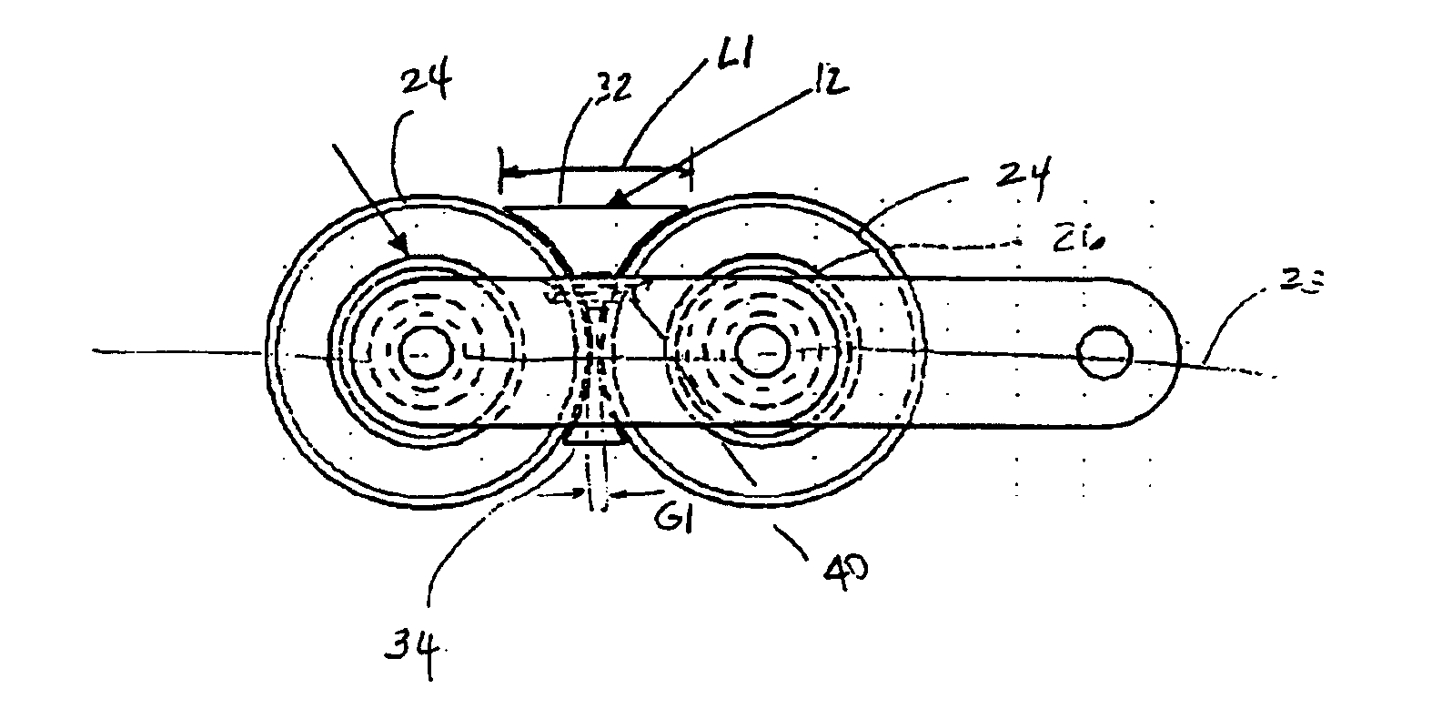
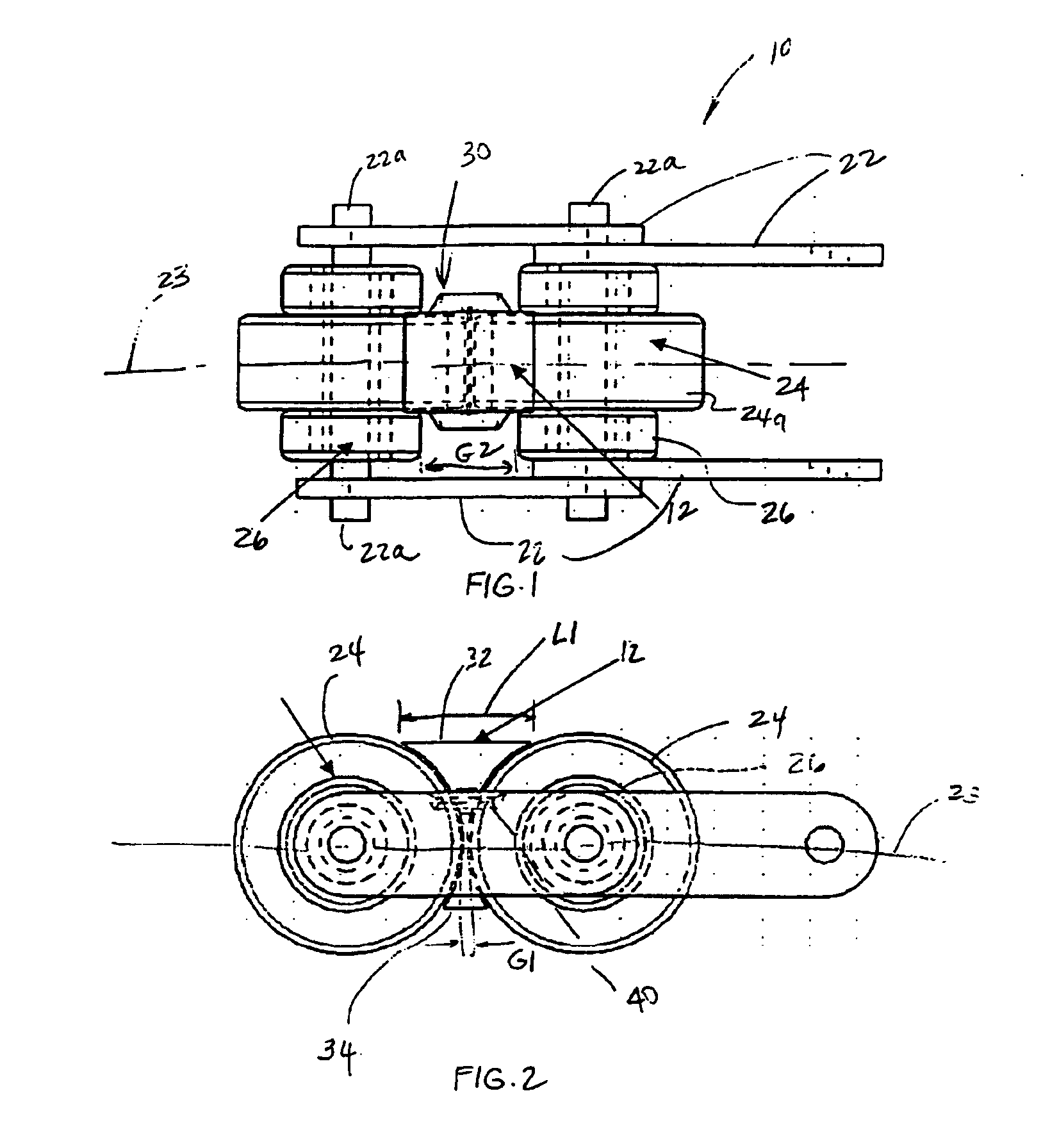
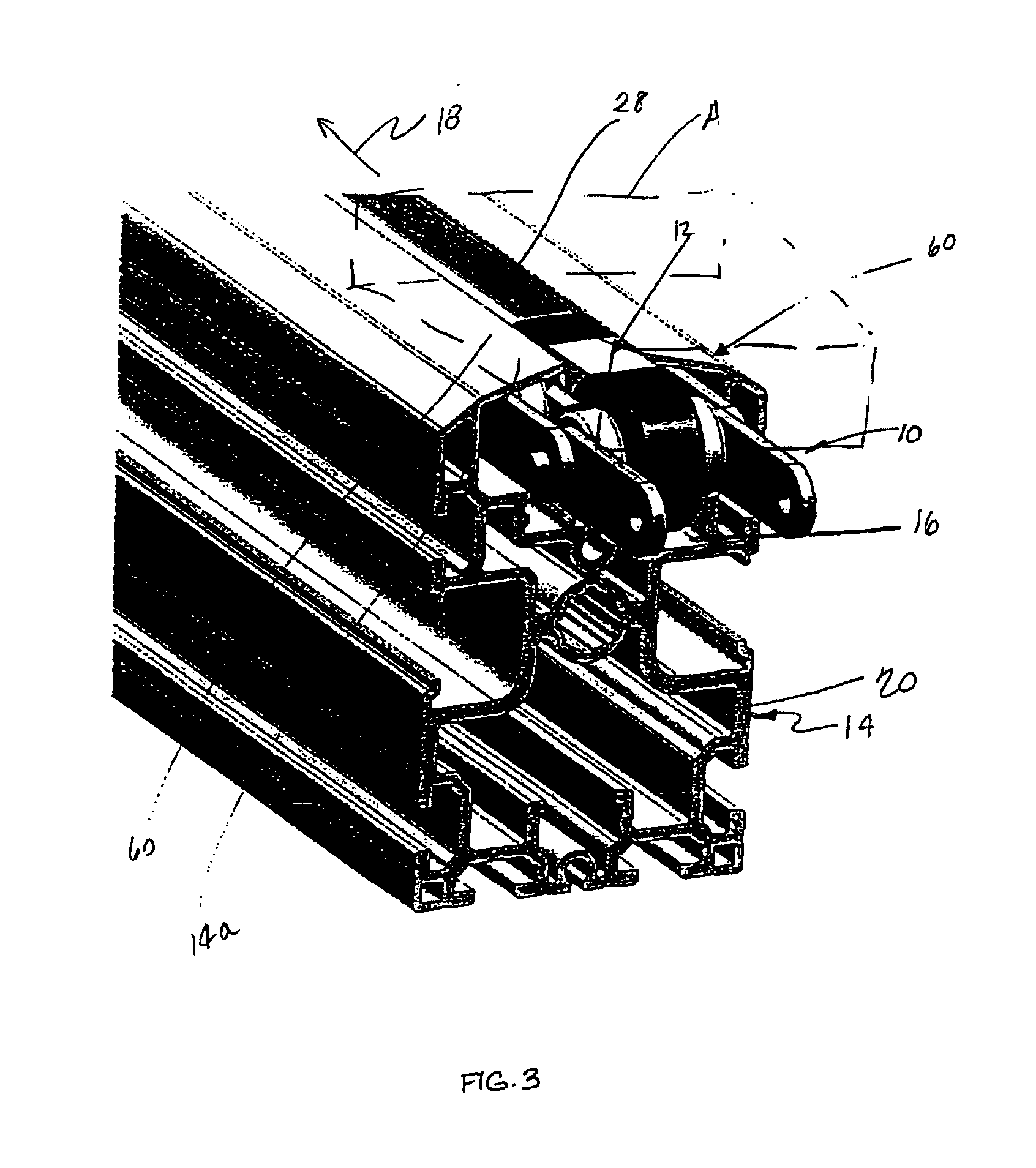
[0029]Referring to FIGS. 1-7, the numeral 10 generally designates a chain conveyor of the present invention. As will be more fully described below, chain conveyor 10 incorporates a plurality of clips 12 that reduces the risk of small items from being caught or trapped in the chain conveyor while minimizing the impact on the flexibility of chain conveyor 10. As best understood from FIG. 3, chain conveyor 10 is typically extended through an extruded member 14 and, more particularly, extended through an upper run 16 of extruded member 14 for conveying an article A along a conveying axis 18 using load rollers 24, described more fully below. Chain conveyor 10 preferably forms a closed loop within extruded member 14 and on its return path extends through lower run 20 to form the closed loop through extruded member 14. As would be understood by those skilled in the art, chain conveyor 10 is driven by a sprocket drive assembly (not shown).

[0030]As best seen in FIGS. 1 and 2, chain conveyor ...


PUM


Abstract

A chain conveyor includes a plurality of load rollers, a plurality of drive rollers, which are arranged in pairs, and a pair of spaced apart rows of interconnecting linkages aligned generally parallel to the longitudinal axis of the chain conveyor. The load rollers and the drive rollers are rotatably mounted between the linkages with the load rollers positioned between the pairs of drive rollers. The diameter of each load roller is larger than the diameter of each drive roller. The load rollers and the drive rollers are spaced along the longitudinal axis wherein the chain conveyor includes gaps between the outer surfaces of adjacent load rollers and between the outer surfaces of adjacent driver rollers. The chain conveyor further includes a clip, which is supported by the load rollers and includes a substantially rigid body, which has an upper surface spanning between the outer surfaces of adjacent load rollers with a length along the longitudinal axis greater than the gap between the adjacent load rollers to thereby substantially close the gap between the adjacent load rollers. The body also includes a lower surface, which spans between the outer surfaces of adjacent load rollers and has a length along the longitudinal axis greater than the gap between the adjacent load rollers to thereby prevent the clip from being ejected from between the adjacent load rollers.

Description

[0001]This application claims priority from U.S. provisional Pat. Application Ser. No. 60 / 480,323, filed Jun. 20, 2003, entitled CHAIN CONVEYOR AND CLIP, by Applicants Michael L. Gambrell and Ray B. Tompkins, and is incorporated herein by reference in its entirety.TECHNICAL FIELD AND BACKGROUND OF THE INVENTION[0002]The present invention relates to a chain conveyor and, more particularly, to a chain conveyor with a protective covering.[0003]Conventional chain conveyors include a plurality of drive rollers and a plurality of load rollers, which are positioned between the drive rollers and, further, which extend above the drive rollers for conveying articles. A chain conveyor is typically extended through an extruded member, which provides support surfaces for the drive rollers and a gap through which the load rollers extend for conveying the articles. Chain conveyors tend to be used in groups of two or more depending on the width and shape of the articles being conveyed. The load rol...

Claims


Application Information

Patent Timeline
IPC IPC(8): B65G17/30B65G17/00B65G17/24
CPCB65G17/24B65G17/30B65G2207/40
Inventor GAMBRELL, MICHAEL LEETOMPKINS, RAY BRADLEY
Owner AUTOMATION & MODULAR COMPONENTS
Why Eureka
Try Eureka