Temperature information detecting device for angle sensor and position detecting device

a technology of temperature information and position information, applied in the direction of operating means/releasing devices of valves, instruments, heat measurement, etc., can solve the problems of increasing costs and achieve the effect of high accuracy

Inactive Publication Date: 2005-05-24
YAMATAKE HONEYWELL CO LTD
View PDF15 Cites 98 Cited by
  • Summary
  • Abstract
  • Description
  • Claims
  • Application Information

AI Technical Summary

Benefits of technology

[0020]According to the present invention, it allows a temperature compensation with high accuracy for the output of the angle sensor based on the temperature information directly obtained from the added result of the middle-point potentials of two bridges of the bridge circuit.

Problems solved by technology

Multiple input signals to be A / D converted requires an A / D converter with many channels and results in increased cost.

Method used


Image

  • Temperature information detecting device for angle sensor and position detecting device
  • Temperature information detecting device for angle sensor and position detecting device
  • Temperature information detecting device for angle sensor and position detecting device

Examples


first embodiment

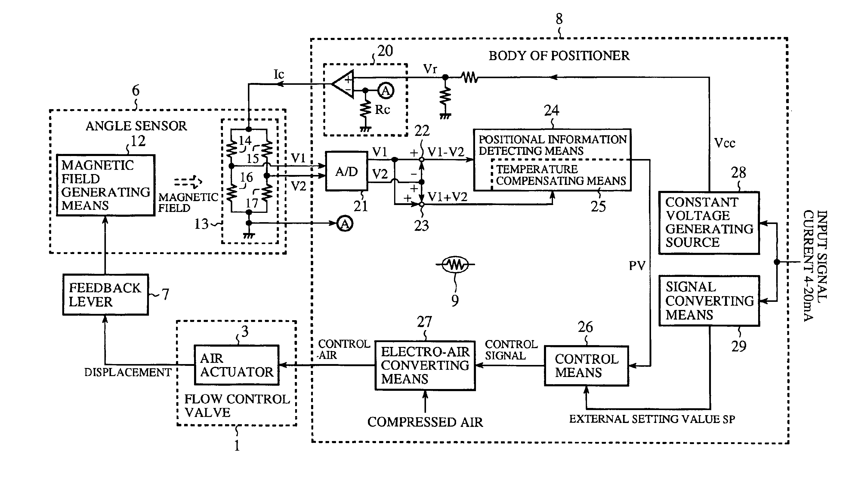
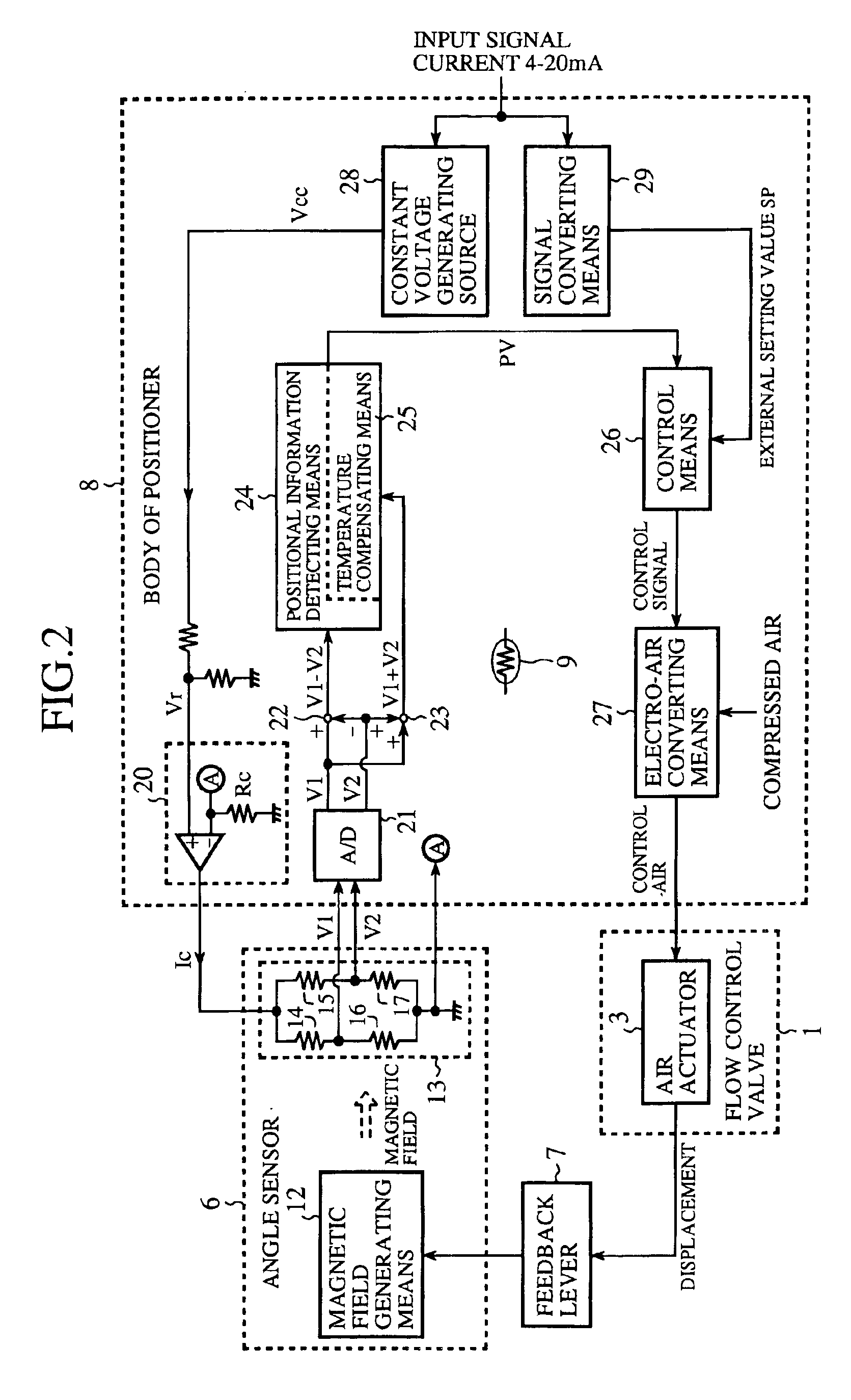
[0029]The first embodiment is directed to detect the valve opening of a flow control valve based on the output of an angle sensor to which a constant current is supplied. Then, an automatic control is done so that the valve opening of the flow control valve coincides with the valve opening setting valve based on the detected valve opening and the valve opening setting value given from the outside. At this time, the temperature compensation is made by using the output of the angle sensor without separately providing any additional temperature sensor.

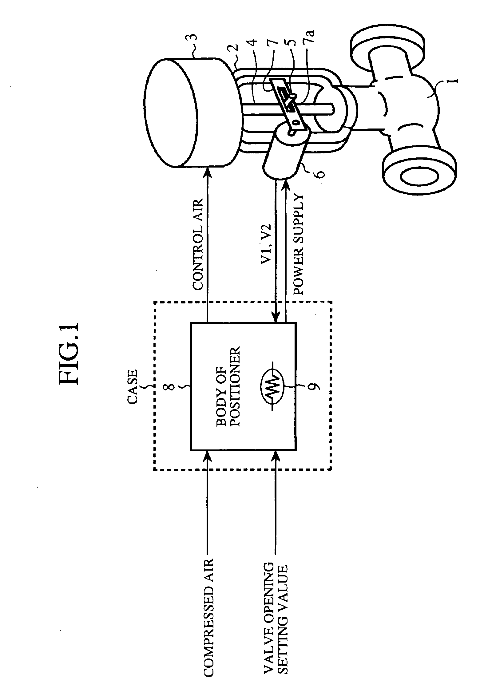
[0030]FIG. 1 is a block diagram showing the flow control valve having the structure where the body of the positioner is separated from the angle sensor, to which the temperature information detecting device for the angle sensor and the position detecting device of the first embodiment are applied. In comparison with the conventional FIG. 3, the first embodiment shown in FIG. 1 is different in that a case of the body of the positioner 8 is...


PUM

PropertyMeasurementUnit
temperatureaaaaaaaaaa
magnetic fieldaaaaaaaaaa
constant electric currentaaaaaaaaaa

Abstract

A temperature information detecting device for an angle sensor is provided for detecting only temperature-dependent components based on middle-point potentials when a constant current is supplied to a bridge circuit for an angle sensor, for acquiring a temperature of the angle sensor from the temperature-dependent components, for employing compensating information corresponding to the acquired temperature without separately providing any additional temperature sensor, and for making temperature compensation of the output of the temperature sensor in automatically controlling the valve opening of a flow control valve.

Description

BACKGROUND OF THE INVENTION[0001]1. Field of the Invention[0002]This invention relates to a temperature information detecting device for an angle sensor and a position detecting device, more particularly to a temperature information detecting device for an angle sensor suitable for control of valve opening of a flow control valve and to a position detecting device using the temperature information detecting device.[0003]2. Description of the Related Art[0004]Conventionally, it has been made a habit in a flow control valve of detecting its valve opening by an angle sensor, of calculating the amount of control of the valve opening by the body of a positioner, a valve opening control device, based on the detected valve opening and a valve opening setting value given from the outside, and of automatically controlling the valve opening in order that it coincides with the valve opening setting value in accordance with the amount of control.[0005]FIG. 3 is a block diagram showing the conve...

Claims


Application Information

Patent Timeline
Patent Type & Authority Patents(United States)
IPC IPC(8): F16K37/00G01K7/36G01D3/028G01D5/18
CPCF16K37/0083
Inventor NOMIYAMA, TAKASHINAGASAKA, FUMIOAKANO, SHINICHI
Owner YAMATAKE HONEYWELL CO LTD
Why Eureka
Try Eureka