Rolling bearing and bearing apparatus

a bearing and rolling bearing technology, applied in the direction of mechanical equipment, bearing units, rotary machine parts, etc., can solve the problems of large torque of bearing apparatus and variations in such rotation torque, large rotation torque, unstable rotation torque, etc., to reduce the number of drawbacks, reduce the number of rotation torque, and reduce the effect of rotation accuracy

Inactive Publication Date: 2005-05-24
NSK LTD
View PDF12 Cites 11 Cited by
  • Summary
  • Abstract
  • Description
  • Claims
  • Application Information

AI Technical Summary

Benefits of technology

[0035]The present invention aims at eliminating the drawbacks found in the Cy above-mentioned related bearing apparatus. Accordingly, it is a first object of the present invention to provide a bearing apparatus which not only is small in rotation torque, and variations in such rotation torque, but also is high in rotation accuracy.
[0036]A second object of the present invention is to provide a rolling bearing in which the incorporating direction of a retainer can be distinguished easily from the outside and the assembling direction of the bearing can be controlled positively according to the incorporating direction of the retainer. A third object of the present invention is to provide a bearing apparatus which not only can maintain the proper quantity of a lubricant, to thereby stabilize the friction torque of the bearing, but also can control an increase in the temperature thereof and the friction thereof.
[0037]A fourth object of the present invention is to provide a bearing apparatus which can satisfy the need for reduction in noise and vibrations thereof, as well as for reduction in the dynamic friction torque thereof.
[0046]According to a sixth aspect of the present invention, there is provided a rolling bearing comprising: an inner ring having an inner raceway formed in an outer peripheral surface thereof; an outer ring having an outer raceway formed in an inner peripheral surface thereof; a plurality of rolling elements rotatably interposed between the inner raceway and the outer raceway; a crown-shaped retainer for holding the rolling elements at regular intervals; and a seal ring interposed between the inner and outer rings for sealing grease or lubricating oil filled into a bearing space or for preventing dust from being generated to the outside, wherein an indicating arrangement, which allows the incorporating direction of the retainer to be distinguished, is provided on one of the axial-direction end faces thereof.

Problems solved by technology

However, when the bearing apparatus of this type is rotated, since the lubricant (a grease as a representative example) is filled in the raceways, the rotation torque of the bearing apparatus and variations in such rotation torque are large.
Also, the grease G, which has been scraped once, is easy to be involved with the rotational movement of the ball 600, which causes the rotation torque to be unstable and large.
However, in the above related bearing apparatus, there are still found problems to be solved: that is, when it is rotated, the rotation torque thereof and variations in the rotation torque are large; and vibrations not synchronous with the rotation of the bearing apparatus are also large.
Due to this, the friction torque of the bearing is large when compared with a bearing of a rolling element guide type including a spherical-shaped retainer pocket, which raises a problem to be solved.
And, in the case where the scraping operation advances excessively due to the high-speed rotation, cutting of an oil film occurs in the pocket edge portion and ball surface to cause poor lubrication.
And due to poor lubrication, there are produced strange sounds.
However, in the case of a bearing using such a retainer, similarly to the above-mentioned retainer including a cylindrical-shaped pocket, there is found a problem that the friction torque of the bearing is large.
However, the related bearing apparatus has become more and more difficult to meet such reduction needs.
However, in the bearing apparatus of this type, there is still found a problem: that is, when it is rotated, since the lubricant is sealed in the grooves of the two bearings, the rotation torque of the apparatus and the variations of the rotation torque are large.
Additionally, vibrations not synchronous with the rotation (NRRO) of the apparatus are large.
That is, simply by reducing the contact angle in the above-described manner, the dynamic friction torque of the bearing caused by the high-speed rotation of the bearing can not be restricted sufficiently.

Method used


Image

  • Rolling bearing and bearing apparatus
  • Rolling bearing and bearing apparatus
  • Rolling bearing and bearing apparatus

Examples


sixth embodiment

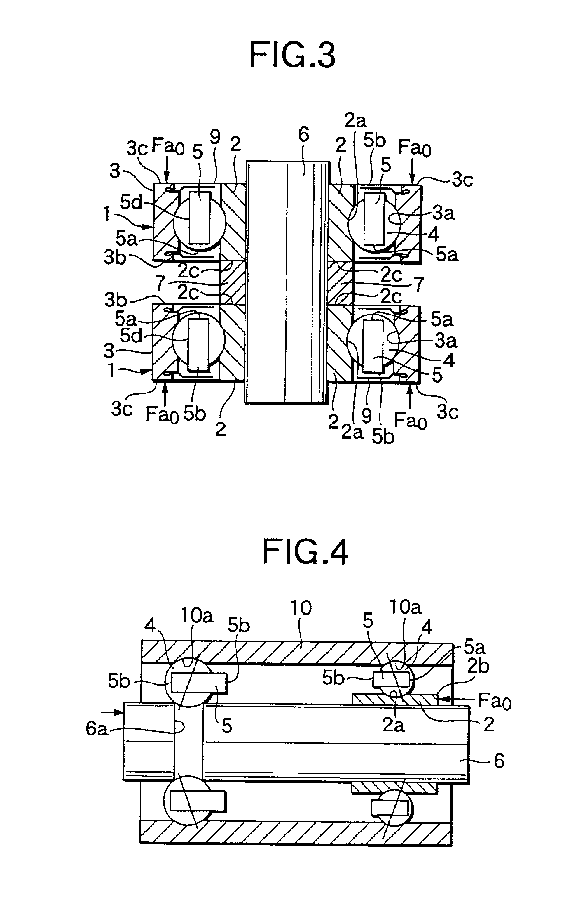
[0138]FIG. 8 shows a sixth embodiment of a bearing apparatus according to the present invention.

[0139]A bearing apparatus according to the present embodiment comprises: a shaft 6 having a double row raceway 6a, 6a formed in the outer periphery thereof; a housing 10 having a raceway 10a so form red in one portion of the inner periphery thereof as to be opposed to one raceway 6a of the shaft 6; an outer ring 3 formed separately from, and fixable to, the inner periphery of the housing 10 opposed to the other raceway 6a of the shaft 6 in such a manner that the two raceways 3a, 6a, are opposed to each other; and, a plurality of rolling elements (balls) 4 . . . , 4 . . . incorporated between the raceway 10a of the housing 10 and one raceway 6a of the shaft 6, as well as between the other raceway 6a of the shaft 6 and the raceway 3a of the outer ring 3 through the crown-shaped retainers 5 and 5.

[0140]In the present embodiment, in FIG. 8, the left side of the housing 10 is held and the sepa...

seventh embodiment

[0142]FIG. 9 shows a seventh embodiment of a bearing apparatus according to the present invention.

[0143]The present embodiment provides a similar structure to the previously described sixth embodiment, but is different therefrom in that the housing 10 has a stepped portion.

[0144]The remaining structures, method for applying the preload. and the operation effects, of the present embodiment are the same as those in the sixth embodiment.

eighth embodiment

[0145]FIG. 10 shows an eighth embodiment of a bearing apparatus according to the present invention.

[0146]According to the present embodiment, there is provided a bearing apparatus which comprises: a stepped housing 10 having a raceway 10a formed in one portion of the inner periphery thereof; a stepped shaft 6 having a raceway 6a so formed in one portion of the outer periphery thereof as to be opposed to the raceway 10a; and, a plurality of rolling elements (balls) 4 . . . incorporated between the raceway 10a of the housing 10 and the raceway 6a of the shaft 6 through a crown-shaped retainer 5; and, a single ball bearing 1 in which an outer ring 3 is fixed to the stepped portion of the housing 10, an inner ring 2 is fixed to the shaft 6, and a plurality of rolling elements 4 . . . are incorporated between the outer and inner rings 3 and 2 through a crown-shaped retainer 5. The present embodiment is substantially similar in structure to the previously described fifth embodiment. Howev...


PUM


Abstract

In a bearing apparatus which is composed of two bearings each including a crown-shaped retainer and in which a lubricant is filled into its raceways, a preload is applied from the retainer pocket-opening side end face of an inner ring, and also a preload is applied from the retainer counter-pocket-opening side end face of an outer ring.

Description

BACKGROUND OF THE INVENTION[0001]The present invention relates to an improvement in a bearing apparatus for use in various kinds of rotary equipment such as a spindle motor (which is also referred to as SPM) which is applied to, for example, a hard disk drive apparatus (which is also referred to as HDD) or a video cassette recorder (which is also referred to as VCR).[0002]The present invention relates to a rolling bearing and a bearing apparatus for use in a small-sized motor which is used mainly in information equipment and home appliances.[0003]The present invention relates to a reduction not only in the vibrations and noises, but also to a reduction in the dynamic friction torque of the bearing apparatus which is used to support a motor shaft such as a spindle provided in a HDD and a drum spindle provided in a VCR.[0004]The present invention relates to a ball bearing and a bearing apparatus for a small-sized motor which is used in a HDD, a VCR, or a laser beam printer (which is a...

Claims


Application Information

Patent Timeline
Patent Type & Authority Patents(United States)
IPC IPC(8): F16C19/56F16C23/00F16C43/04F16C35/12F16C33/66F16C35/00F16C43/00F16C33/38F16C23/08F16C33/41F16C19/02F16C19/16F16C19/00
CPCF16C19/56F16C33/416F16C35/12F16C25/08F16C19/547F16C33/6607F16C41/008F16C43/04F16C19/06F16C2240/40F16C25/083F16C2240/42
Inventor ISHIWADA, HIROSHIAOKI, MAMORUMIYAZAKI, SEIZOUNAWAMOTO, TAIKOUARAMAKI, HIROTOSHI
Owner NSK LTD
Why Eureka
Try Eureka