Drywall sanding implement

Inactive Publication Date: 2005-05-24
TURGEON ROBERT J
View PDF5 Cites 16 Cited by
  • Summary
  • Abstract
  • Description
  • Claims
  • Application Information

AI Technical Summary

Benefits of technology

[0017]An abrasive coating is applied to the outer surface of the body. Preferably, the body and the abrasive coating are configured with respect to each of the first pair of opposed corners of the substantially parallelogram-shaped cross section so as to prevent contact of the abrasive coating at each of the first pair of opposed corners with a surface being abraded. Such a configuration minimizes the chances of the surface being abraded becoming scarred or gouged by one of the first pair of opposed corners.
[0018]One configuration of the body and abrasive coating which has been found effective in preventing scarring, when the cross section of the body is a parallelogram, is to make the abrasive coating discontinuous at each of the first pair of opposed corners. This may be accomplished by making the abrasive coating discontinuous per se, or by making the coating continuous while eliminating the abrasive grains at the first pair of o

Problems solved by technology

One problem with such devices is that the long shaft is unwieldy, making sanding in tight areas difficult.
However, such interchangeability requires complicated structure and appears to be prone to breakage under heavy usage.
A problem with all such devices is the use of sandpaper.
When used for smoothing drywall joints, sandpaper quickly loses its abrasive capability, and is prone to tearing on electrical junction boxes or other protrusions from the drywall surface.
The effort required to replace the sandpaper is

Method used


Image

  • Drywall sanding implement
  • Drywall sanding implement
  • Drywall sanding implement

Examples


Embodiment Construction

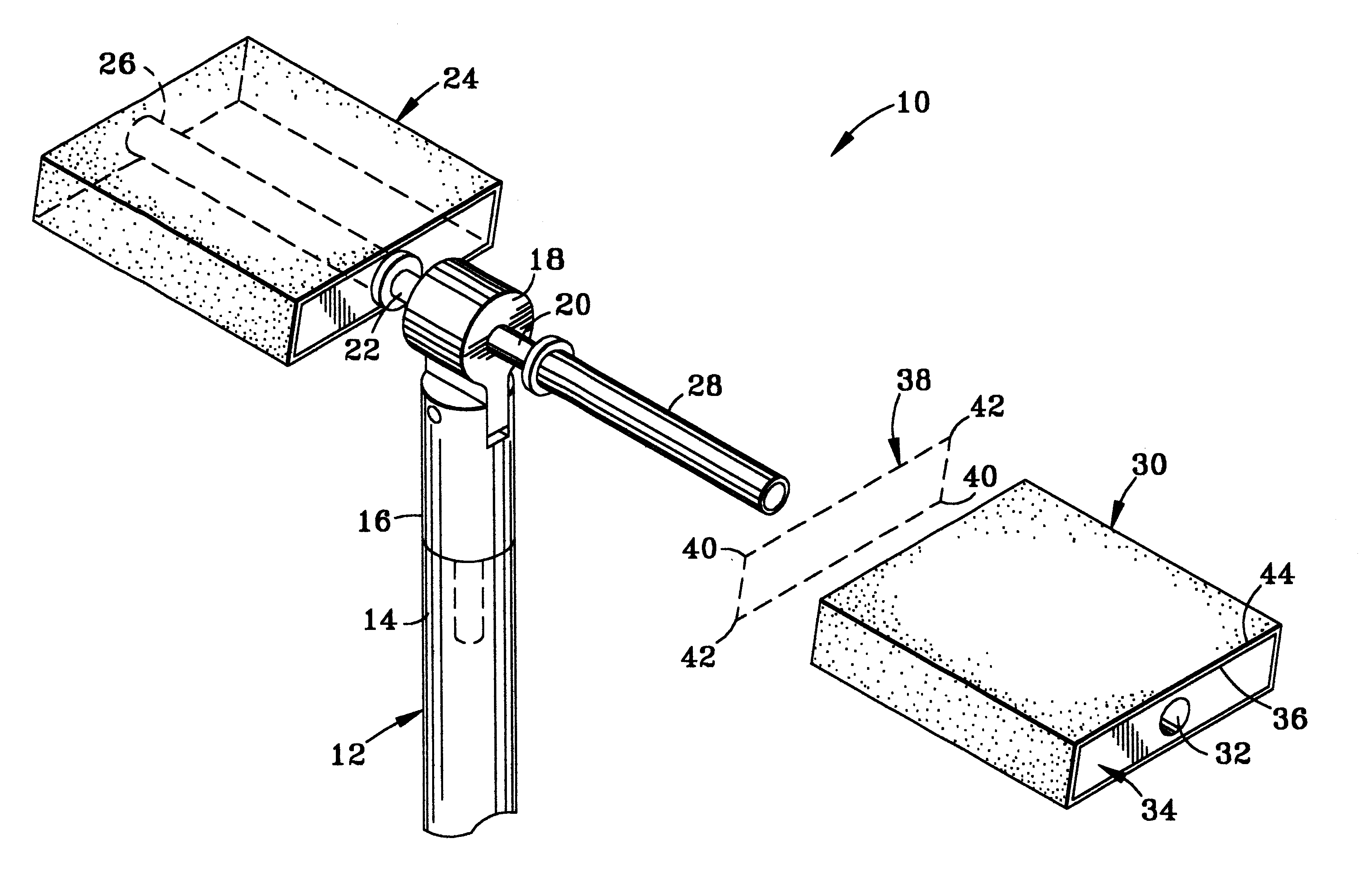
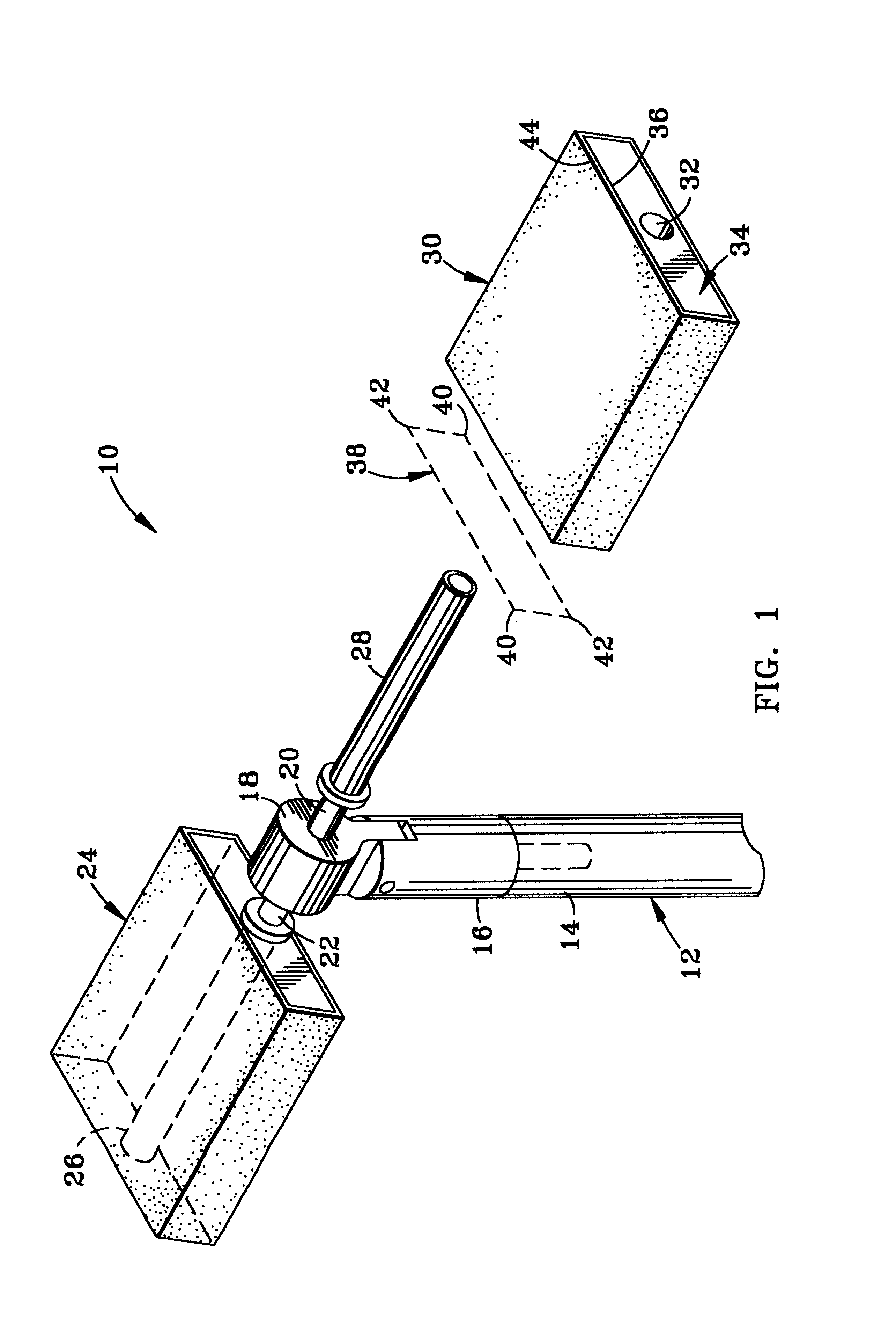
[0024]FIG. 1 illustrates one embodiment of the present invention, a drywall sanding implement 10. The drywall sanding implement 10 is designed for attachment to a shaft 12 having a first end 14.

[0025]The drywall sanding implement 10 has a yoke 16 which is attachable to the first end 14 of the shaft 12. A block 18 is pivotably mounted to the yoke 16.

[0026]An axle 20 is mounted to the block 18. A first spindle 22 is rotatably mounted to the axle 20. The first spindle 22 may be retained on the axle 20 by means of a cotter pin, E-clip, or various other means well known in the art.

[0027]A first pad 24 is provided, which has a first pad mounting passage 26 therethrough. The first pad mounting passage 26 is configured to frictionally engage the first spindle 22, allowing the first pad 24 to readily be removed or replaced onto the first spindle 22.

[0028]Similarly, a second spindle 28 is also rotatably mounted to the axle 20. A second pad 30 having a second pad mounting passage 32 therethrou...


PUM


Abstract

A drywall sanding implement having a shaft, a yoke attached to the shaft, a block pivotably mounted to the yoke, a pair of spindles mounted to the block, and a sanding block removably mounted on each spindle.

Description

CROSS REFERENCE TO OTHER APPLICATIONS[0001]This application claims the benefit of a U.S. Provisional Application filed by Express Mail, Number FF851564952US, on Oct. 21, 1997.FEDERALLY SPONSORED RESEARCH AND DEVELOPMENT[0002]There are no federally sponsored or funded research or development projects or undertakings in any way associated with the instant invention.BACKGROUND OF THE INVENTION[0003]1. Field of the Invention[0004]The present invention is for a drywall sanding implement and an abrasive pad for use with the same. The drywall sanding implement has particular utility for smoothing joints in drywall construction.[0005]2. Background Information[0006]Sanding poles are frequently used for smoothing joints in drywall construction. During construction, the joints between the panels of drywall are filled with joint compound. The joint compound is allowed to dry, and then abraded with sandpaper to achieve a smooth wall surface. A sanding pole allows the user to sand joints from flo...

Claims


Application Information

Patent Timeline
IPC IPC(8): B24D15/00B24D15/04
CPCB24D15/04
Inventor TURGEON, ROBERT J.DAWSON, CLIFFORD F.
Owner TURGEON ROBERT J
Why Eureka
Try Eureka