Instrumentation and methods for use in implanting a cervical disc replacement device

a cervical disc and implanting technology, applied in the field of spine arthroplasty, can solve the problems of undesirable progressive fusion of a long sequence of vertebrae, significant pain to the individual suffering from the condition,

Inactive Publication Date: 2005-05-24
HOWMEDICA OSTEONICS CORP
View PDF11 Cites 296 Cited by
  • Summary
  • Abstract
  • Description
  • Claims
  • Application Information

AI Technical Summary

Benefits of technology

[0024]Once the construct is properly positioned in the treatment area, the surgeon uses an insertion pusher of the present invention to disengage the insertion handle shaft from the stem of the insertion plate. The insertion pusher has a longitudinal shaft with a blunt distal end and a proximal end with a flange. The shaft of the insertion pusher can be inserted into and translated within the longitudinal bore of the insertion handle shaft. Because the shaft of the insertion pusher is as long as the longitudinal bore of the insertion handle shaft, the flange of the insertion handle and the flange of the insertion pusher are separated by a distance when the pusher shaft is inserted all the way into the longitudinal bore until the blunt distal end of the shaft contacts the proximal face of the insertion plate stem. Accordingly, a bringing together of the flanges (e.g., by the surgeon squeezing the flanges toward one another) will overcome the friction lock between the distal end of the insertion handle shaft and the stem of the insertion plate.
[0028]Once the mounting screws and the insertion plate are removed, the surgeon uses a clip applicator of the present invention to mount retaining clips on the flanges to assist in retaining the bone screws. Each of the clips has a central attachment bore and, extending therefrom, a pair of oppositely directed laterally extending flanges and an upwardly (or downwardly) extending hooked flange. The clips can be snapped onto the element flanges (one clip onto each flange). Each of the laterally extending flanges of the clip is sized to cover at least a portion of a respective one of the bone screw heads when the clip is attached in this manner to the flange so that the clips help prevent the bone screws from backing out.

Problems solved by technology

This degeneration of this critical disc material, from the hydrated, elastomeric material that supports the separation and flexibility of the vertebral bones, to a flattened and inflexible state, has profound effects on the mobility (instability and limited ranges of appropriate motion) of the segment, and can cause significant pain to the individual suffering from the condition.
Unfortunately, until the advent of spine arthroplasty devices, the only methods known to surgeons to maintain the necessary disc height necessitated the immobilization of the segment.
Either way, however, it is clear that a progressive fusion of a long sequence of vertebrae is undesirable from the perspective of the patient's quality of life as well as from the perspective of pushing a patient to undergo multiple operative procedures.

Method used


Image

  • Instrumentation and methods for use in implanting a cervical disc replacement device
  • Instrumentation and methods for use in implanting a cervical disc replacement device
  • Instrumentation and methods for use in implanting a cervical disc replacement device

Examples


Embodiment Construction

[0052]While the invention will be described more fully hereinafter with reference to the accompanying drawings, it is to be understood at the outset that persons skilled in the art may modify the invention herein described while achieving the functions and results of the invention. Accordingly, the descriptions that follow are to be understood as illustrative and exemplary of specific structures, aspects and features within the broad scope of the invention and not as limiting of such broad scope. Like numbers refer to similar features of like elements throughout.

[0053]A preferred embodiment of a cervical disc replacement device of the present invention, for use with the instrumentation of the present invention, will now be described.

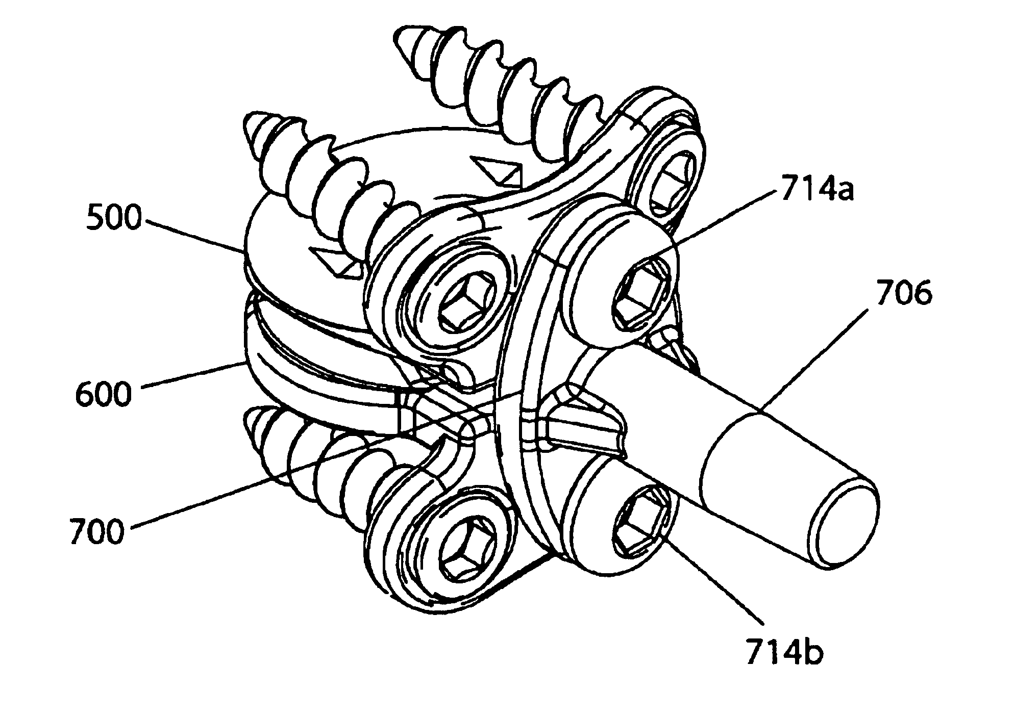
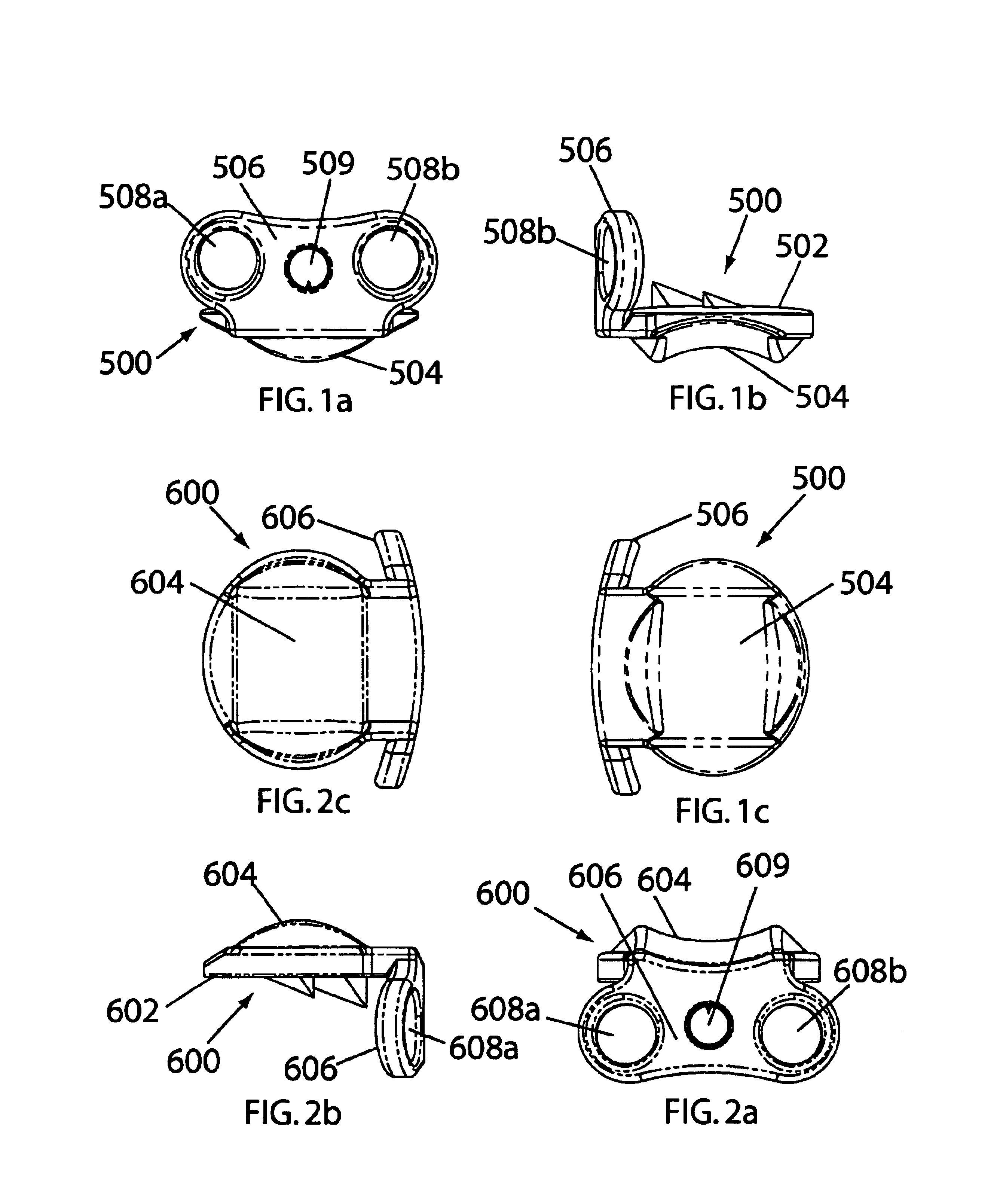
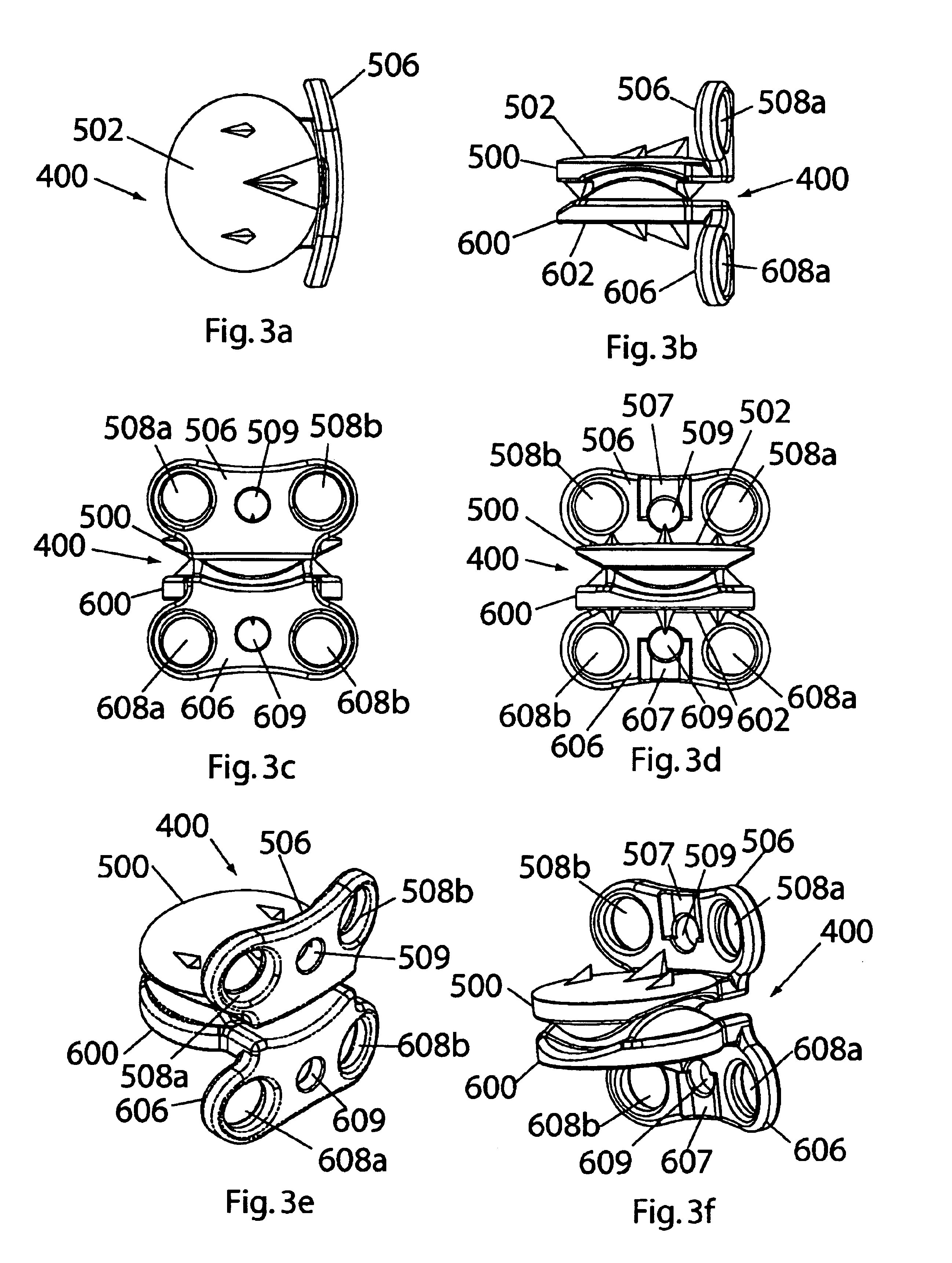
[0054]Referring now to FIGS. 1a-3f, a top element 500 of the cervical disc replacement device 400 is shown in anterior (FIG. 1a), lateral (FIG. 1b), and bottom (FIG. 1c) views; a bottom element 600 of the cervical disc replacement device 400 is shown in ...


PUM


Abstract

Instrumentation for implanting a cervical disc replacement device includes cervical disc replacement trials for determining the appropriate size of replacement device to be implanted, an insertion plate for maintaining the elements of the replacement device in fixed relation to one another for simultaneous manipulation, an insertion handle for attachment to the insertion plate for manipulation of the elements, an insertion pusher for releasing the insertion handle from the insertion plate, a drill guide that cooperates with the insertion plate to guide the drilling of tap holes for bone screws to be placed through bone screw holes in the flanges of the replacement device, clips that are applied to the flanges after placement of the bone screws to resist screw backout, and a clip applicator for applying the clips to the flanges.

Description

CROSS-REFERENCE TO RELATED APPLICATIONS[0001]The present application is a continuation-in-part application of U.S. patent application Ser. No. 10 / 382,702 (filed Mar. 6, 2003) entitled “Cervical Disc Replacement” (“the '702 application”), which is hereby incorporated by reference herein in its entirety.FIELD OF THE INVENTION[0002]This invention relates generally to systems and methods for use in spine arthroplasty, and more specifically to instruments for inserting and removing cervical disc replacement trials, and inserting and securing cervical disc replacement devices, and methods of use thereof.BACKGROUND OF THE INVENTION[0003]The structure of the intervertebral disc disposed between the cervical bones in the human spine comprises a peripheral fibrous shroud (the annulus) which circumscribes a spheroid of flexibly deformable material (the nucleus). The nucleus comprises a hydrophilic, elastomeric cartilaginous substance that cushions and supports the separation between the bones ...

Claims


Application Information

Patent Timeline
Patent Type & Authority Patents(United States)
IPC IPC(8): A61B17/80A61B17/68A61F2/44A61F2/46A61B17/17A61B17/16A61B17/70A61B17/88A61B17/86A61F2/00A61F2/30
CPCA61B17/8033A61B17/8042A61F2/4425A61F2/4611A61F2/4684A61B17/1728A61F2002/30843A61B17/8625A61B17/866A61F2002/30301A61F2002/30578A61F2002/30616A61F2002/3065A61F2002/30841A61F2002/449A61F2002/4627A61F2002/4628A61F2002/4629A61F2230/0095Y10S623/908Y10S623/911A61B17/7059A61F2230/0065A61F2/442A61F2002/4625
Inventor ZUBOK, RAFAILDUDASIK, MICHAEL W.ERRICO, JOSEPH P.
Owner HOWMEDICA OSTEONICS CORP
Why Eureka
Try Eureka