Liquid separator with holder unit

a technology of liquid separator and holder unit, which is applied in the field of liquid separator, can solve the problems of unavoidable sample accompanying moisture, secretion, blood, bacteria, etc., and difficulty in obtaining a filter surfa

Inactive Publication Date: 2005-05-24
SHENZHEN MINDRAY BIO MEDICAL ELECTRONICS CO LTD
View PDF19 Cites 73 Cited by
  • Summary
  • Abstract
  • Description
  • Claims
  • Application Information

AI Technical Summary

Benefits of technology

[0011]Accordingly, the object of the present invention is to provide a liquid separator that avoids the aforesaid drawback with the earlier known water trap.

Problems solved by technology

When a gas sample from expiration gases is led in a patient circuit to an analysis instrument, it is unavoidable that moisture, secretion, blood, bacteria, etc., are liable to accompany the sample.
Should water, blood or secretion enter the analysis instrument, there is a serious risk that the instrument will be permanently damaged, and consequently various protective solutions for preventing such contamination have been proposed in the art.
One drawback with this solution resides in the difficulty of obtaining a filter surface, which is sufficiently large to prevent the rise time of the gas measuring process from being impaired.
A filter that has a small surface area will quickly become blocked and there-with result in an interruption in the gas monitoring process.
The presence of a bacteria filter in the orifice of the sampling conduit will not solve the moisture problem, because the moisture does not precipitate from the sample until the sample is downstream of the filter.
This material, however, is very expensive which makes it difficult to obtain viable products when using said material.
However, one drawback with this solution is that the rise time of the gas measuring process will be seriously impaired unless the water trap is adapted with respect to the volume of gas that shall be processed at that particular time.
The pneumatic rise time of the gas sampling system is essentially inversely proportional to the sampling flow, in other words a high rate of flow results in a short rise time.
Consequently, when the need for a short rise time is greatest, the possibilities of achieving such a rise time are the worst.
Consequently, if the instrument is left switched on for a long period of time in the absence of a protective filter, the measuring chamber of the analyser will gradually become dirty with progressively poorer performances as a result.
One drawback with this known water trap is that it requires a relatively large filter area, about 1 cm2, in order to ensure that the product will have a sufficient length of life.
Hoses used for gas sampling purposes, however, will normally have an inner diameter of about 1.4–1.5 mm, meaning that eddy currents are generated and impaired rise time obtained when the gas sample reaches the larger diameter of the passageway.

Method used


Image

  • Liquid separator with holder unit
  • Liquid separator with holder unit
  • Liquid separator with holder unit

Examples


Embodiment Construction

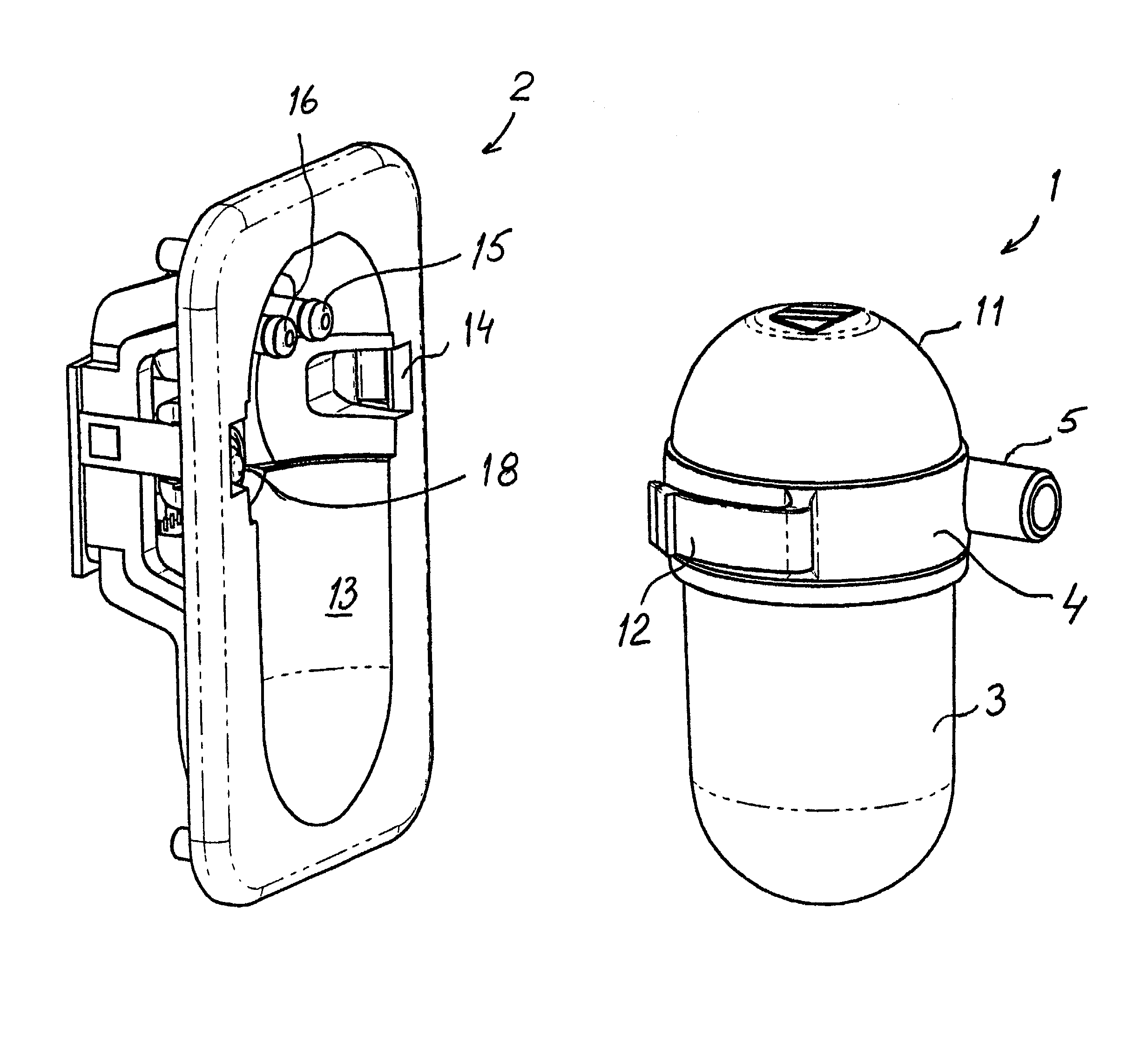
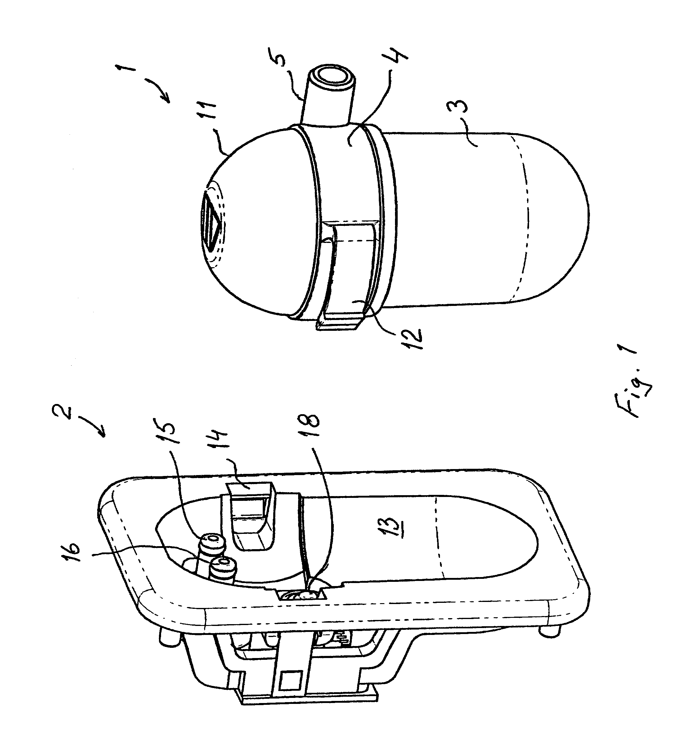
[0019]The inventive liquid separator comprises two main parts in the form of a water trap 1 and a holder unit 2. The holder unit 2 is a part that can normally be firmly fitted to the instrument (not shown) used to analyse expiration gas. The water trap 1 is a disposable product that is preferably found in two different sizes or two different designs, one for adult patients and one for neonatal patients.

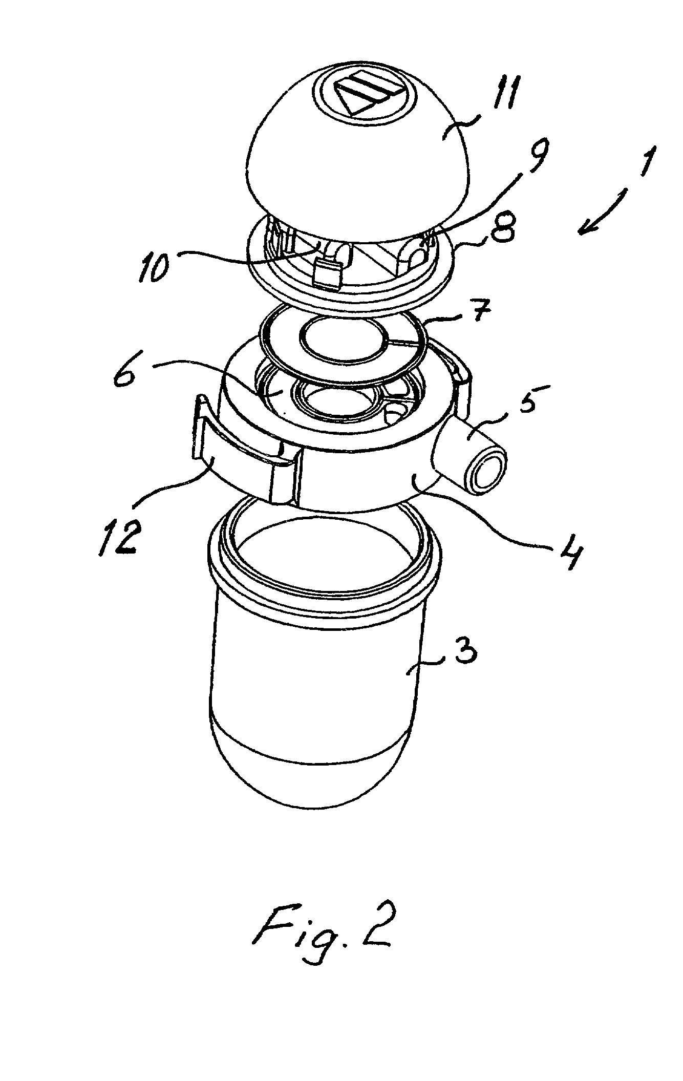
[0020]The water trap 1 includes a container 3 located beneath a separation chamber 4 provided with a connection 5 for receiving a gas flow incoming from the patient. The separation chamber includes a liquid passageway 6 and a filter 7 positioned above said passageway, for instance a bacteria filter. Located above the separation chamber 4 and connecting to the other side of the filter 7 is an upper chamber part 8 that includes a gas passageway (not shown) corresponding to the liquid passageway 6 in the separation chamber and leading to connection passageways 9, 10 by which the water tr...


PUM

PropertyMeasurementUnit
rise timeaaaaaaaaaa
rise timeaaaaaaaaaa
flow rateaaaaaaaaaa

Abstract

A liquid separator for separating liquid from gases, comprises a water trap (1) that includes a container (3), a connector (5) for incoming gas flow, a separation chamber (4) that includes a filter and at least one connection passageway for leading separated gas to an analysis instrument. The water trap (1) can be removably fitted in a holder unit (2) connected to the analysis instrument, and the holder unit (2) includes connection devices (15, 16) for receiving the connection passageway.

Description

BACKGROUND OF THE INVENTION[0001]The present invention relates to a liquid separator for separating liquid from gases, and particularly for separating liquids from expiration gases in medical analysis instruments. The invention includes a liquid separator having a water trap and a holder / connection device. The water trap may be a one time use only trap, and the connection device may be a quick-fastener device.DESCRIPTION OF THE RELATED ART[0002]When a gas sample from expiration gases is led in a patient circuit to an analysis instrument, it is unavoidable that moisture, secretion, blood, bacteria, etc., are liable to accompany the sample. As the temperature falls when the gas sample is led from the patient circuit to the analysis instrument, moisture present in the gas precipitates in the form of water droplets. Should water, blood or secretion enter the analysis instrument, there is a serious risk that the instrument will be permanently damaged, and consequently various protective ...

Claims


Application Information

Patent Timeline
Patent Type & Authority Patents(United States)
IPC IPC(8): A61B5/097A61B5/08A61M16/08A61M16/18A61M16/10
CPCA61B5/097A61M16/0808A61M16/085A61M2209/082A61M16/186A61M16/1055A61M16/107
Inventor ECKERBOM, ANDERSLINDESTAM, PER
Owner SHENZHEN MINDRAY BIO MEDICAL ELECTRONICS CO LTD
Why Eureka
Try Eureka