Molding process and apparatus for producing unified composite structures

a composite material and process technology, applied in the field of molding process and apparatus, can solve the problems of increasing the cost of manufacturing the structure, not being able to form such structures in a single step molding procedure, etc., and achieve the effect of durable and light weight structur

Inactive Publication Date: 2005-05-24
THE BOEING CO
View PDF28 Cites 65 Cited by
  • Summary
  • Abstract
  • Description
  • Claims
  • Application Information

AI Technical Summary

Benefits of technology

[0007]Once the stitched-together dry fiber preform assembly is fully infused with resin, it is then cured inside a suitable oven for a predetermined period of time to allow the resin infused into the stitch-together assembly to thoroughly cure. When removed from the tool, the stitched-together assembly forms a finished, unitary part. The bladders may then be extracted through small holes formed at various portions of the assembly such as holes within rib webs of the assembly if the assembly includes such webs. The resulting unitized structure thus forms a single piece structural assembly that is co-cured and reinforced with z-direction stitching. Accordingly, no subsequent manufacturing steps involving bonding of individual molded details or elements or mechanical fastening of individual molded panels together is required. The co-curing and the stitching of the independent dry fiber material forms together to create a single piece unit further eliminates local stress concentrations at the interfaces of independent component sections of the assembly and results in a more durable, light weight structure that is especially well suited for use in high-performance aircraft manufacturing applications.

Problems solved by technology

Due to the size and complexity of structural components such as aircraft wings, sections of aircraft fuselage, etc., the formation of such structures using composite materials in a single step molding procedure has historically not been possible.
The cost to manufacture the structure thus increases significantly through the additional manufacturing steps needed to fabricate separately and then assemble (i.e., often bond adhesively or mechanically attach) two or more independent component parts to form a single overall structure.

Method used


Image

  • Molding process and apparatus for producing unified composite structures
  • Molding process and apparatus for producing unified composite structures
  • Molding process and apparatus for producing unified composite structures

Examples


Embodiment Construction

[0014]The following description of the preferred embodiment(s) is merely exemplary in nature and is in no way intended to limit the invention, its application, or uses.

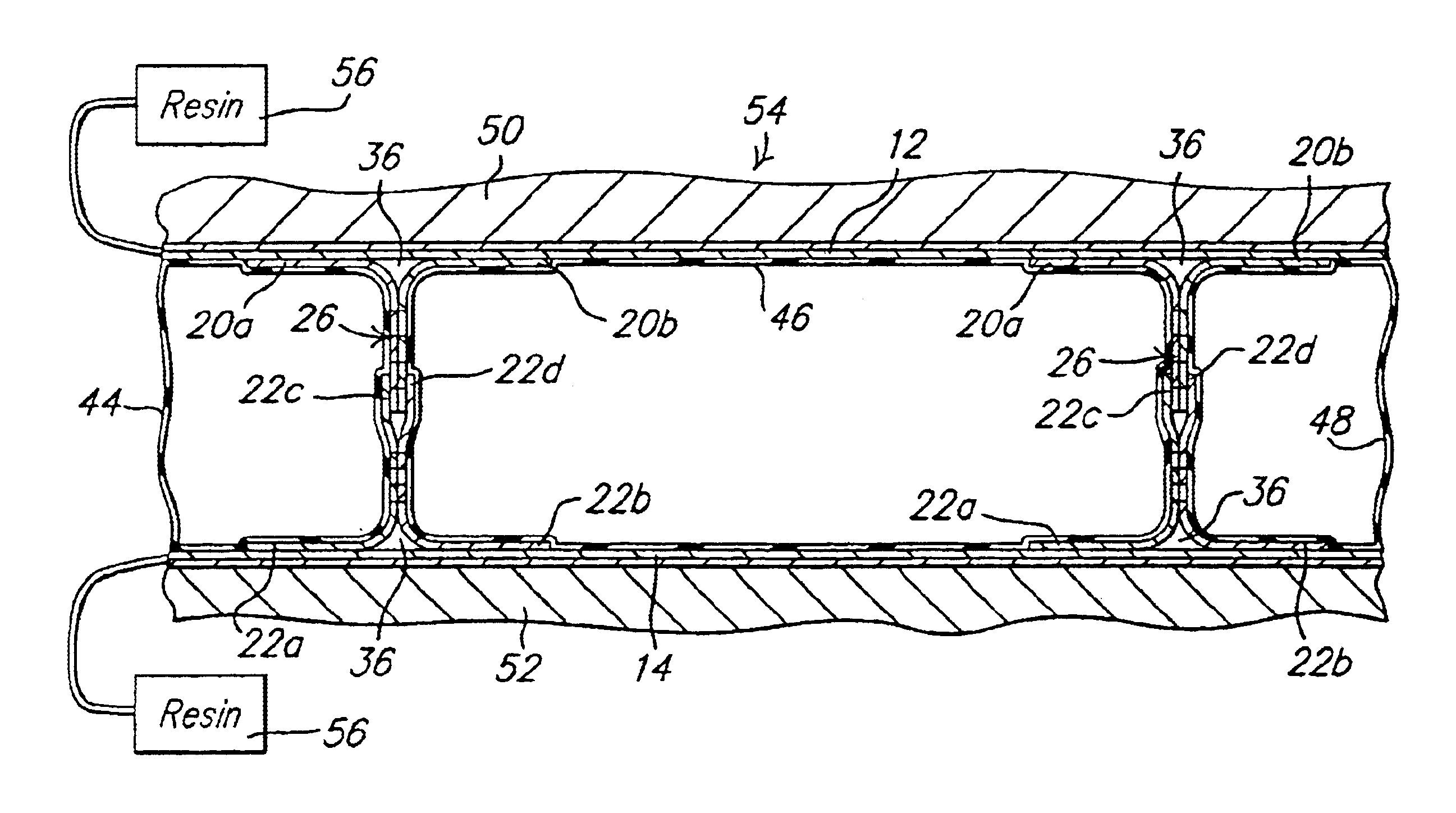
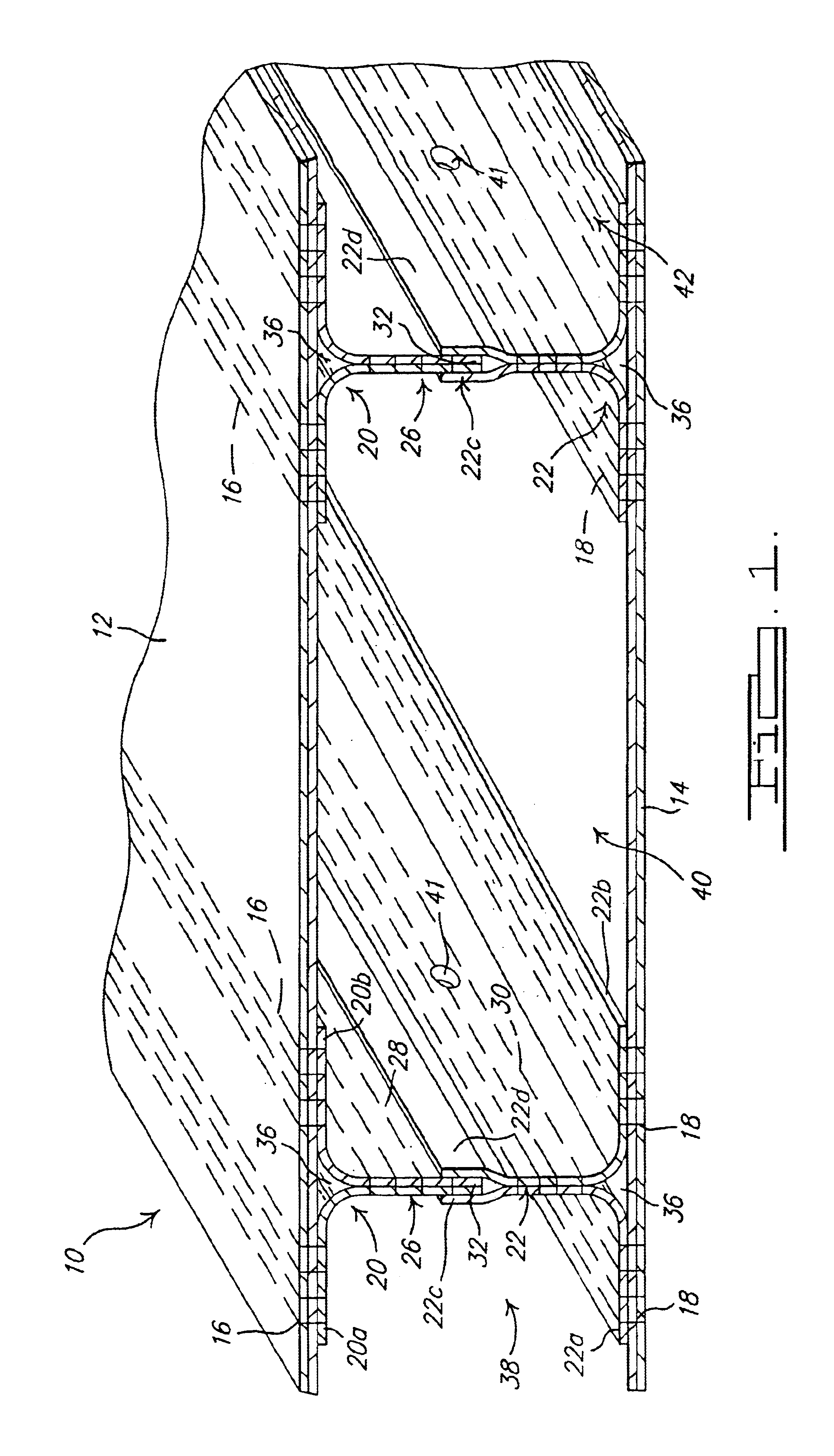
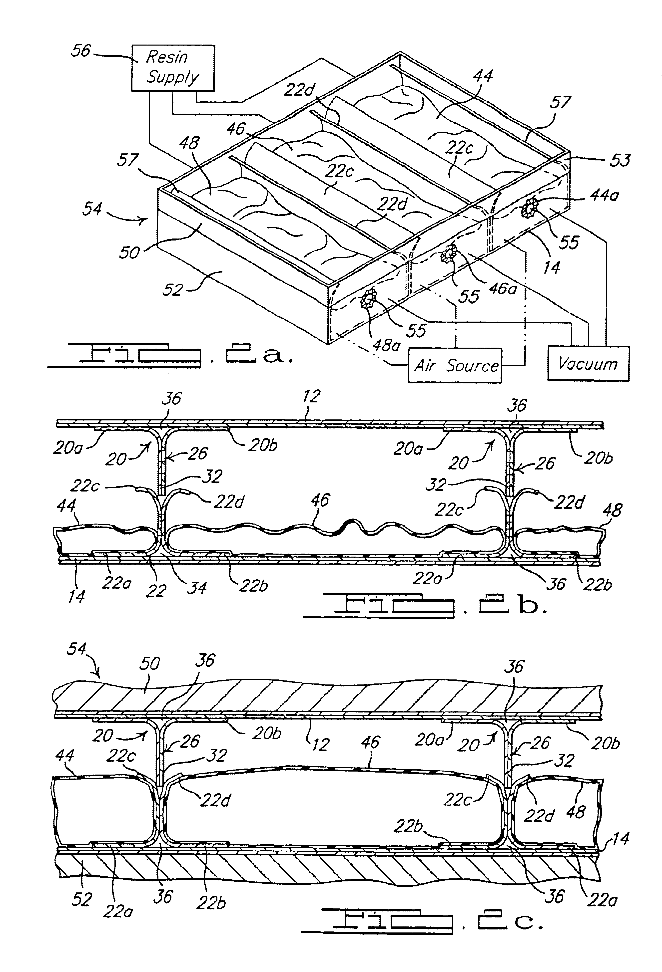
[0015]Referring to FIG. 1, there is shown a structure 10 formed in accordance with a preferred method of the present invention. In this example, structure 10 forms a stiffened box structure, but it will be appreciated immediately that the method of the present invention is not limited to the manufacturer of just stiffened box structures or even just aircraft subassemblies. The method of the present invention can be used to form unified, composite structural assemblies that are suitable for use in a wide variety of applications and for forming a wide variety of structural components. The method of the present invention, however, is especially useful in aircraft manufacturing applications as it significantly reduces the cost and time associated with manufacturing large complex structural parts which heretofore could onl...


PUM

PropertyMeasurementUnit
time periodaaaaaaaaaa
shapeaaaaaaaaaa
temperatureaaaaaaaaaa

Abstract

A method of forming a unitary, composite structural member, and a member formed in accordance with the process. The process involves stitching a plurality of warp knit panel sections together to generally form a plurality of independent panel sections. The sections are placed within the dies of a molding tool such that a rib portion of each section aligns. Inflatable bladders are then slipped into voids formed in between the various panel sections of the assembly. The bladders are inflated to hold with one another. Resin is then infused into the panels that make up the assembly. The assembly is then cured. When the panels are removed from the molding tool a unitary, complexly shaped, composite structural member is formed.

Description

FIELD OF THE INVENTION[0001]This invention relates to molding processes and apparatus', and more particularly to a molding process and apparatus for producing large and complex structural components especially well suited for aircraft structural components through a single step molding process.BACKGROUND OF THE INVENTION[0002]Due to the size and complexity of structural components such as aircraft wings, sections of aircraft fuselage, etc., the formation of such structures using composite materials in a single step molding procedure has historically not been possible. Until recently, a process capable of holding critical dimensional features within narrow tolerance ranges for large complex composite structures did not exist.[0003]In previous manufacturing operations, typically the complex part is broken down into multiple pieces of simple design that are subsequently assembled into a single large complex structure. The cost to manufacture the structure thus increases significantly t...

Claims


Application Information

Patent Timeline
Patent Type & Authority Patents(United States)
IPC IPC(8): B29C70/04B29C70/44B29C65/00B29D24/00
CPCB29C65/00B29C66/54B29C66/721B29C66/81457B29C70/443B29D24/008B29C66/81455Y10T428/24174B29C66/1248B29L2024/006B29L2031/3082B29L2031/3085B29C66/124B29C66/53462Y02T50/433B29C33/505B29C66/112B29C66/1122B29C66/131B29C66/71B29C66/72141B29D99/0014B29C70/304Y02T50/40B29K2007/00
Inventor VELICKI, ALEXANDERTHRASH, PATRICK JOSEPHBURGESS, ROGER ALANSTANDISH, COLE
Owner THE BOEING CO
Why Eureka
Try Eureka