Axial tube assembly of a motor

a technology of axial tube and motor, which is applied in the direction of dynamo-electric machines, structural associations, instruments, etc., can solve the problems of bearing lubricating oil loss, and achieve the effect of reliable assembly and rotational stability

Active Publication Date: 2005-05-24
SUNONWEALTH ELECTRIC MACHINE IND
View PDF3 Cites 22 Cited by
  • Summary
  • Abstract
  • Description
  • Claims
  • Application Information

AI Technical Summary

Benefits of technology

[0006]An object of the present invention is to provide a motor with an axial t...

Problems solved by technology

Further, in a case that the bearings 4 are oily bearings, the axial tube 11 and the engaging member 2 could ...

Method used


Image

  • Axial tube assembly of a motor
  • Axial tube assembly of a motor
  • Axial tube assembly of a motor

Examples


Embodiment Construction

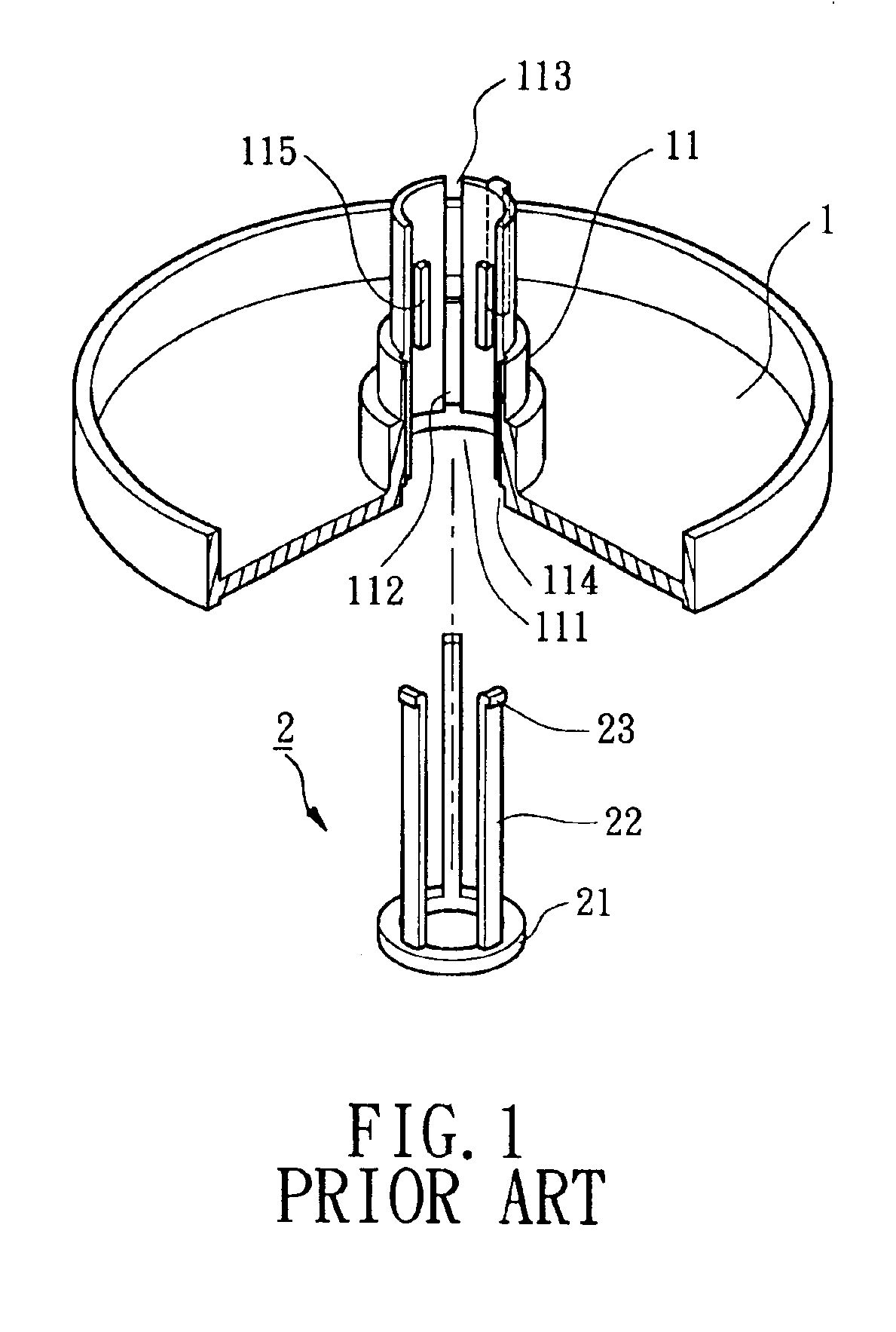
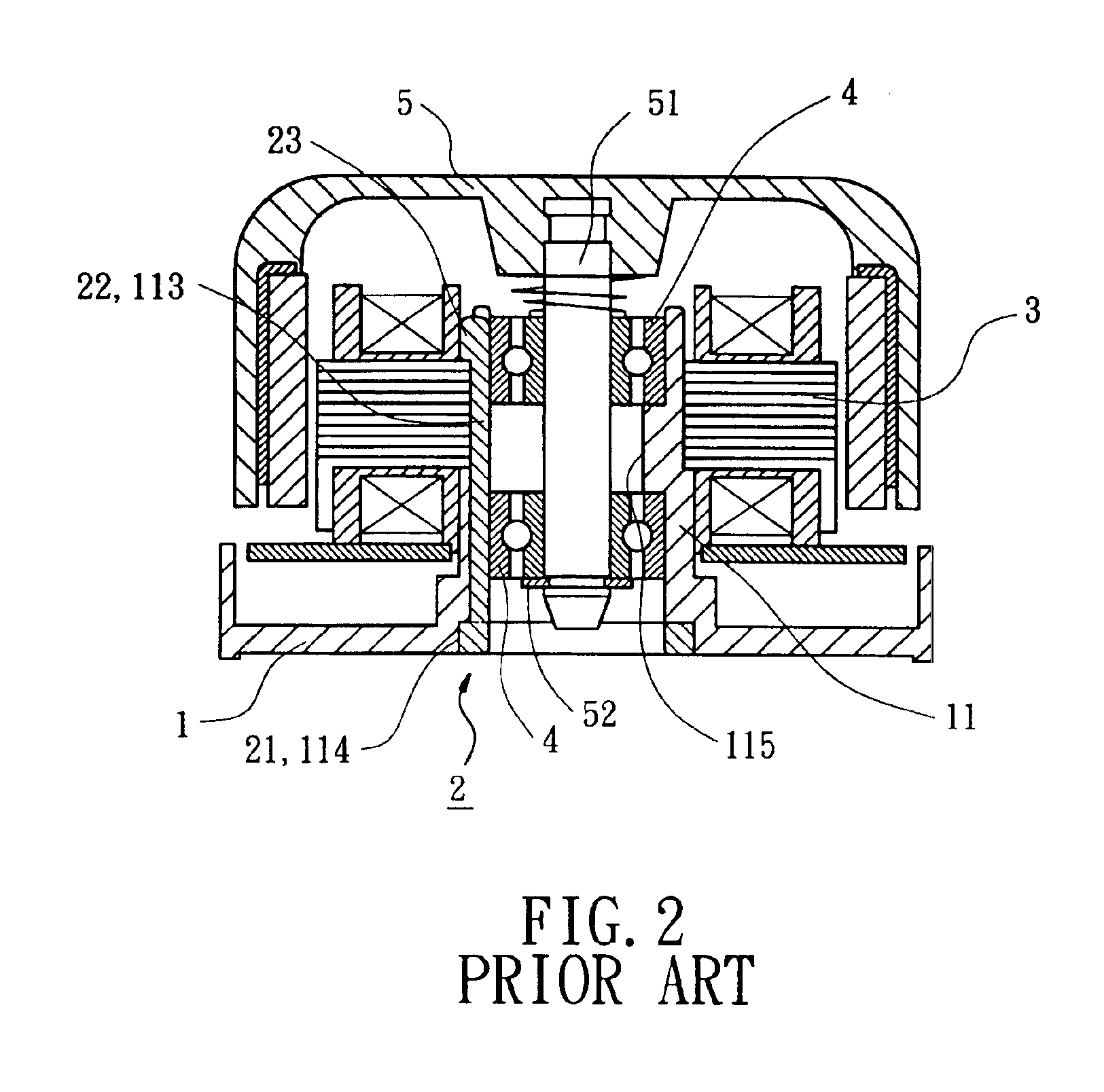
[0029]A preferred embodiment of the present invention is now to be described hereinafter in detail, in which the same reference numerals are used in the preferred embodiments for the same parts as those in the prior art to avoid redundant description.

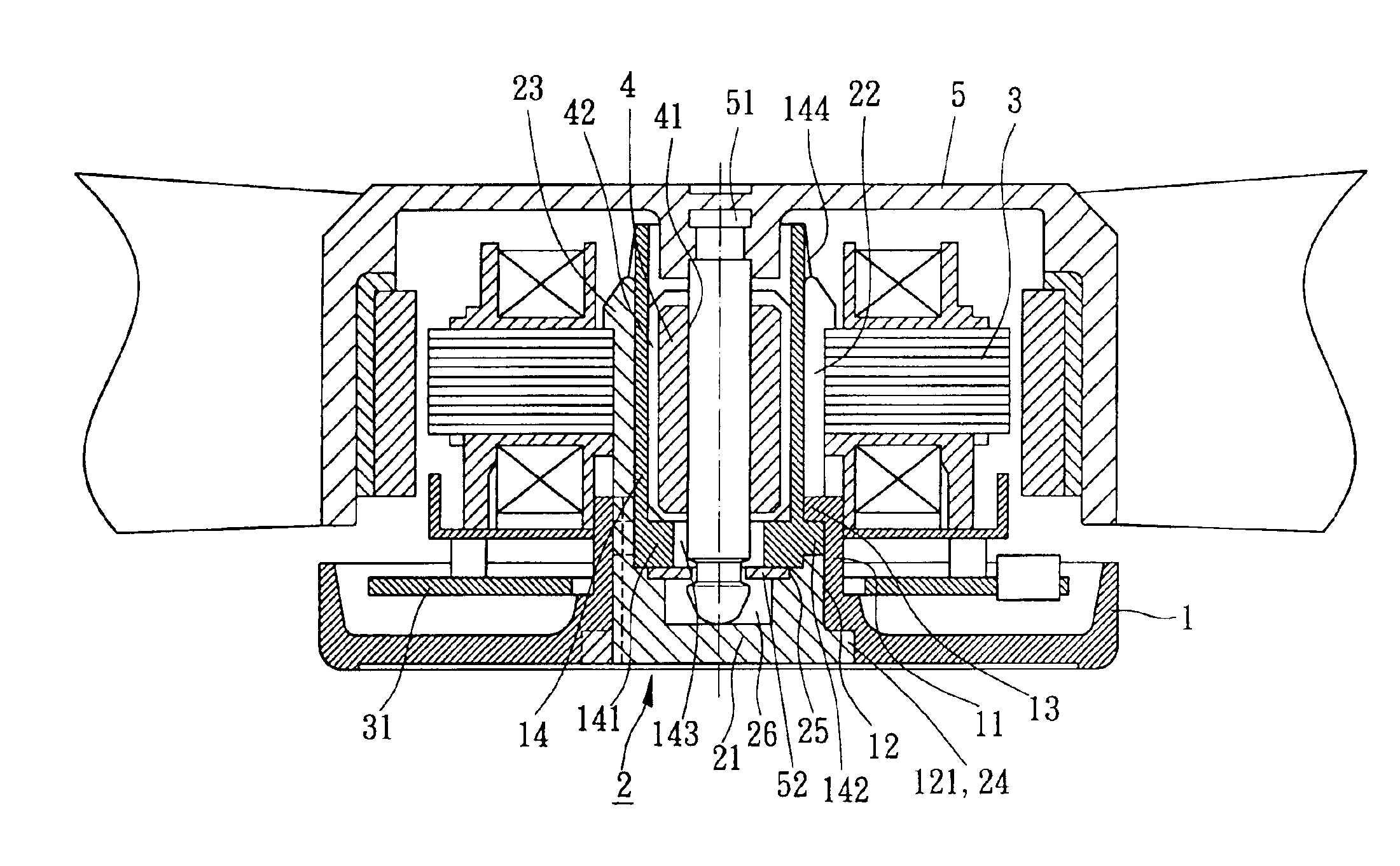
[0030]Referring to FIGS. 3 through 7, a motor in accordance with the present invention comprises a casing 1, a stator assembly 3, a bearing 4, and an axial tube assembly. In this embodiment, the axial tube assembly includes an axial tube 11, an engaging member 2, and a sleeve 14. The axial tube 11 is generally integrally formed on a central portion of the casing 1 and made of plastic. An outer periphery of the axial tube 11 may be smooth or configured to have a stepped portion for mounting the stator assembly 3 and a circuit board 31 of various dimensions. The axial tube 11 has an axial hole 111, with a plurality of grooves 12 being defined in an inner periphery delimiting the axial hole 111, with a plurality of positioning grooves 112 ...


PUM


Abstract

An axial tube assembly of a motor includes an axial tube around which a stator assembly is mounted, an engaging member, and a sleeve in which a bearing is mounted. The engaging member includes a base and a plurality of resilient legs projecting from the base. Each resilient leg has a hook on a distal end thereof. The base of the engaging member is engaged with and thus seals a bottom end of an axial hole of the axial tube. The sleeve is mounted in the engaging member and has a base portion. The hook of each resilient leg is pressed outward to thereby retain the stator assembly in place when the sleeve and the engaging member are received in the axial tube, with the resilient legs of the engaging member together holding the sleeve to thereby allow tight engagement between the sleeve and the bearing.

Description

BACKGROUND OF THE INVENTION[0001]1. Field of the Invention[0002]The present invention relates to an axial tube assembly of a motor.[0003]2. Description of Related Art[0004]FIG. 1 illustrates a conventional axial tube assembly of a motor, and FIG. 2 is a sectional view of a motor with an axial tube assembly of FIG. 1. As illustrated in FIGS. 1 and 2, the motor includes a casing 1 with an axial tube 11 formed thereon. The axial tube 11 has an axial hole 11, wherein plural slots 112 are defined in a periphery delimiting the axial hole 111 and each include an open end 113. An engaging member 2 includes a ring-like base 21 and plural legs 22 projecting from a side of the base 21. The base 21 is engaged in an annular groove 114 in a bottom end of the axial tube 11, with the respective leg 22 being received in the respective slot 112 and with a hook 23 on a distal end of the respective leg 22 pressing against a side of a stator assembly 3 that is mounted around the axial tube 11. Plural pr...

Claims


Application Information

Patent Timeline
IPC IPC(8): H02K7/08H02K5/167H02K5/15
CPCH02K5/15H02K5/1675H02K7/083
Inventor HORNG, ALEXHONG, YIN-RONG
Owner SUNONWEALTH ELECTRIC MACHINE IND
Why Eureka
Try Eureka