Plasma display panel

a display panel and plasma technology, applied in the direction of gas discharge vessels/containers, gas-filled discharge tubes, solid cathodes, etc., can solve the problems of colloidal particles affecting the display performance, reducing the amount of light to be obtained, and unsatisfactory color of the discharge space, so as to enhance the display performance reduce the power consumption of the plasma display panel, and enhance the dielectric layer excellent transparency

Inactive Publication Date: 2005-05-24
PANASONIC CORP
View PDF10 Cites 34 Cited by
  • Summary
  • Abstract
  • Description
  • Claims
  • Application Information

AI Technical Summary

Benefits of technology

[0036]With the above construction, the first dielectric layer effectively suppresses colloidal particles from being deposed out of the plurality of pairs of display electrodes, secures excellent transparency of the dielectric layer, and enhances the display performance of the plasma display panel. The second dielectric layer effectively reduces the power consumption of plasma display panel by reducing the permittivity ∈ value....

Problems solved by technology

This puts an undesired color to the light emitted from the discharge space, or reduces the amount of light to be obtained.
As apparent from the above, the colloidal particles...

Method used


Image

  • Plasma display panel
  • Plasma display panel
  • Plasma display panel

Examples


embodiment 1

1. Embodiment 1

1-1. Entire Construction of PDP

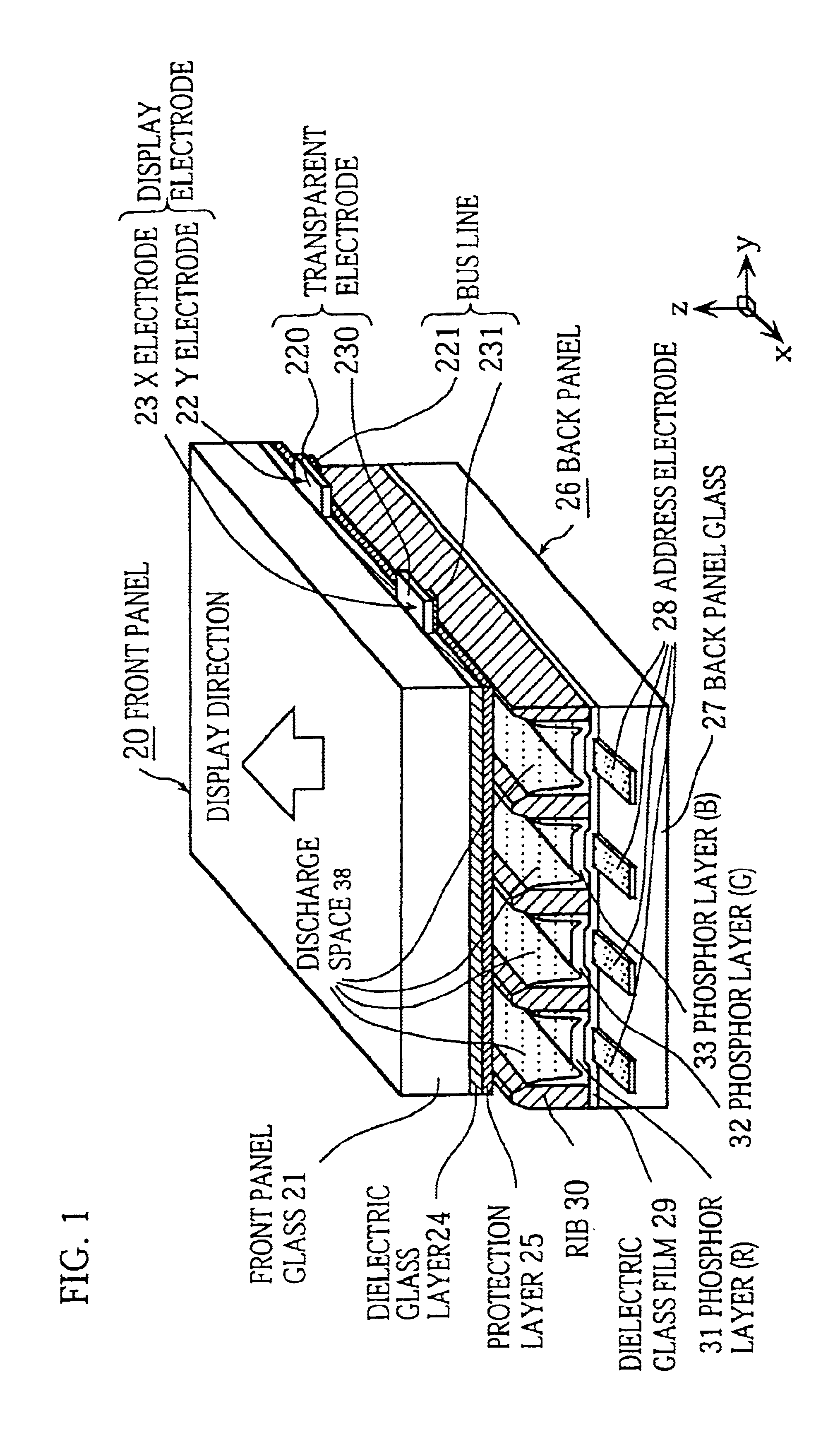
[0041]FIG. 1 is a perspective, sectional view showing main components of the AC surface-discharge type plasma display panel (hereinafter called PDP) in Embodiment 1. In the drawing, the z direction is a direction along thickness of the PDP and the xy plane is parallel to the panel surface of the PDP. Though the size of the PDP in the present embodiment conforms to the VGA specifications for 42-inch class, the present invention can be applied to other sizes as well.

[0042]As shown in FIG. 1, the PDP is roughly divided into the front panel 20 and the back panel 26 which are disposed so that their main surfaces face each other.

[0043]On one surface of the front panel glass 21, which is the substrate of the front panel 20, a plurality of pairs of display electrodes 22 and 23 (an X electrode 23 and a Y electrode 22) are disposed in the x direction, where the y direction is the direction of the length, and each pair of display electrodes 22 and ...

embodiment 2

2. Embodiment 2

[0064]The PDP in Embodiment 2 will be described. The construction of Embodiment 2 is almost the same as Embodiment 1 except for the dielectric layer.

2.1 Construction of Dielectric Layer and Surroundings

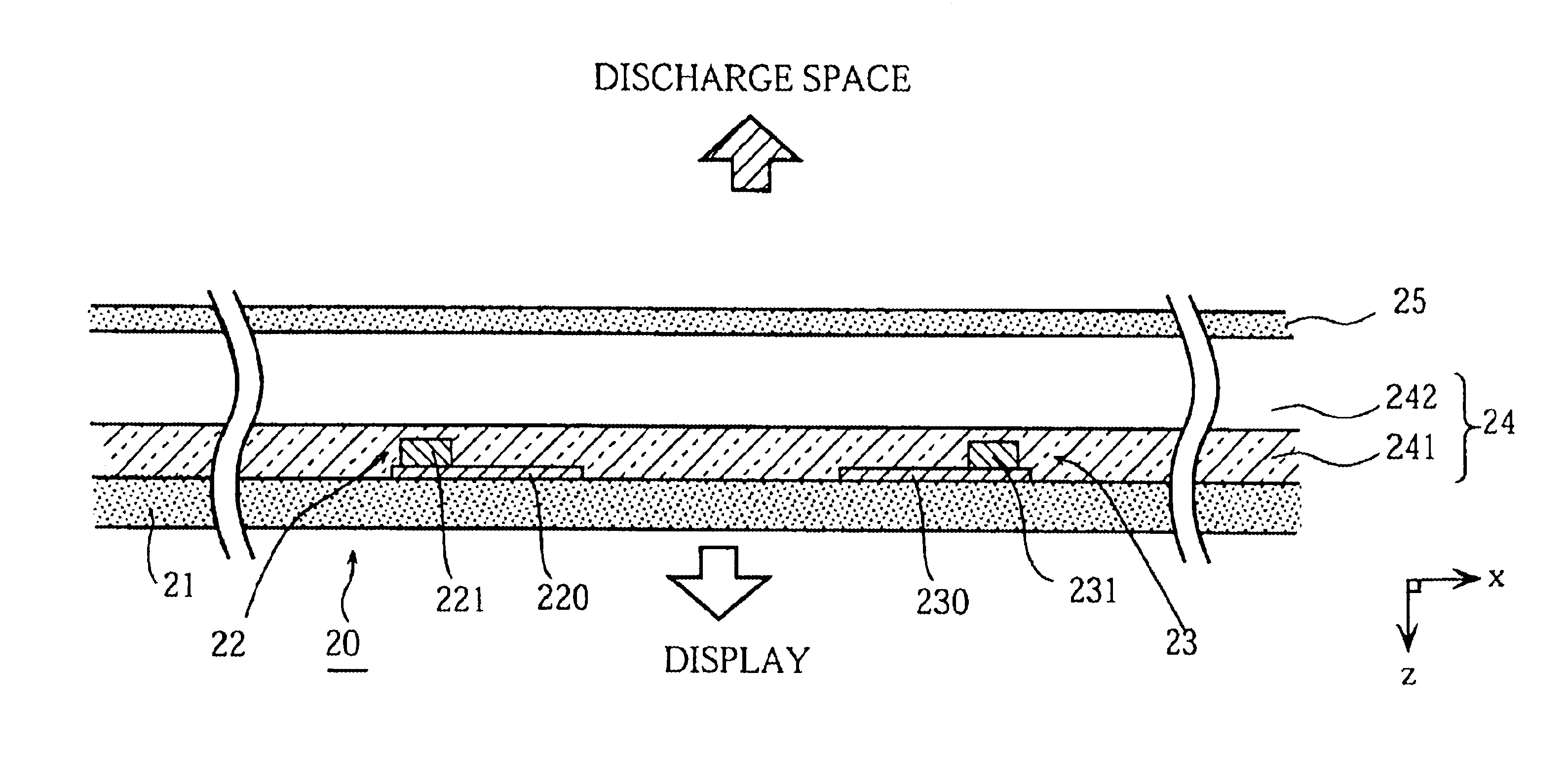
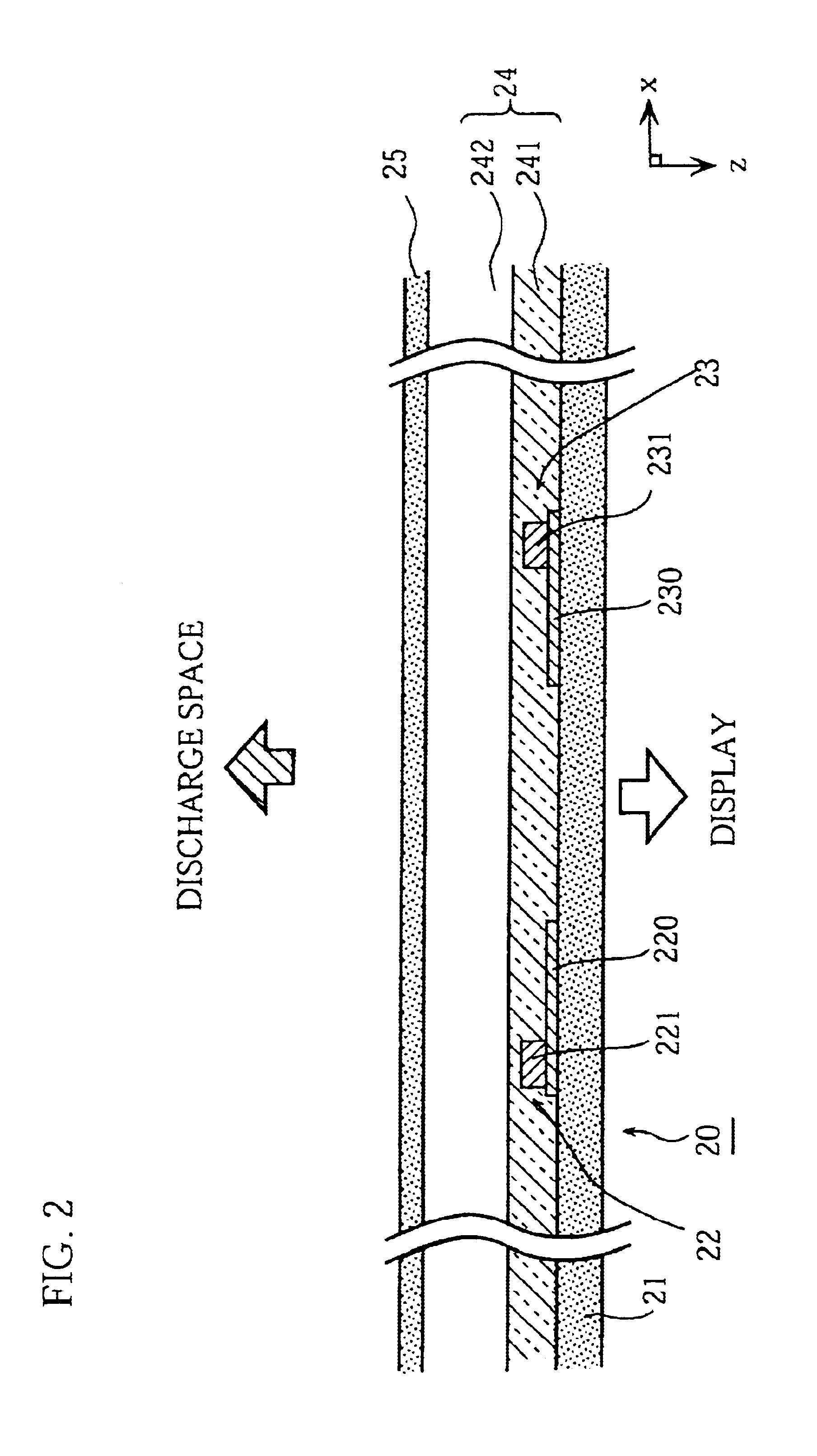
[0065]FIG. 2 is a partial sectional view of the PDP showing a detailed construction of the dielectric layer 24 in Embodiment 2 and the surroundings. As shown in FIG. 2, the dielectric layer 24 in Embodiment 2 has a two-layered construction in which the second dielectric layer 242 is laid on the first dielectric layer 241.

[0066]The first dielectric layer 241 is composed of a 5μm-thick PbO-base glass (which is composed of, in this example, 65 wt % of PbO, 10 wt % of B2O3, 24 wt % of SiO3, 1 wt % of CaO, and 2 wt % of Al2O3), and is formed on the main surface of the front panel glass 21 covering the display electrodes 22 and 23.

[0067]The second dielectric layer 242 is composed of a 25 μm-thick ZnO—P2O5-base glass (which is composed of, in this example, 30 wt % of ZnO, 20 w...


PUM

PropertyMeasurementUnit
Thicknessaaaaaaaaaa
Temperatureaaaaaaaaaa

Abstract

The present invention provides a plasma display panel in which a space between a first plate and a second plate facing each other is filled with a discharge gas, a plurality of pairs of display electrodes made of Ag or Cu are formed on a surface of the first plate facing the second plate, and the surface of the first plate is covered with a dielectric layer covering the plurality of pairs of display electrodes, where the dielectric layer is made of a glass that contains at least ZnO and 10 wt % or less of R2O and does not substantially contain PbO and Bi2O3, and a product of permittivity ε and loss factor tan δ of the dielectric layer is 0.12 or less, wherein R is selected from a group consisting of K, Rb, Cs, Cu, and Ag.

Description

TECHNICAL FIELD[0001]The present invention relates to a plasma display panel used for a display device or the like. More particularly, the present invention relates to a dielectric layer.BACKGROUND ART[0002]Recently, high performance displays such as high-definition (e.g., Hi-Vision) or large-scale displays are much sought after, and various studies are performed for developing high-performance displays such as CRT displays, liquid crystal displays (LCD), and plasma display panel (PDP).[0003]PDP is a kind of gas-discharge panel. To manufacture a PDP, two thin glass plates are disposed to face each other with partition walls (ribs) in between, and a plurality of pairs of display electrodes, a dielectric layer (typically, made of Ag or Cr / Cu / Cr in order to secure good conductivity), and a phosphor layer are formed in this order on the surface of one of the two thin glass plates facing the ribs, then the space between the two thin glass plates is filled with a discharge gas, and the sp...

Claims


Application Information

Patent Timeline
IPC IPC(8): C03C17/02H01J17/49H01J11/36C03C4/16C03C8/04C03C8/08C03C8/10C03C8/16C03C17/04
CPCC03C4/16C03C8/04C03C8/08H01J11/38C03C8/16C03C17/04H01J11/12C03C8/10H01J11/36
Inventor AOKI, MASAKIYAMASHITA, KATSUYOSHIOHTANI, MITSUHIROHIBINO, JUNICHI
Owner PANASONIC CORP
Why Eureka
Try Eureka