
Integral passive shim system for a magnetic resonance apparatus

Inactive Publication Date: 2005-05-24
BRUKER BIOSPIN
View PDF7 Cites 25 Cited by
  • Summary
  • Abstract
  • Description
  • Claims
  • Application Information

AI Technical Summary

Benefits of technology

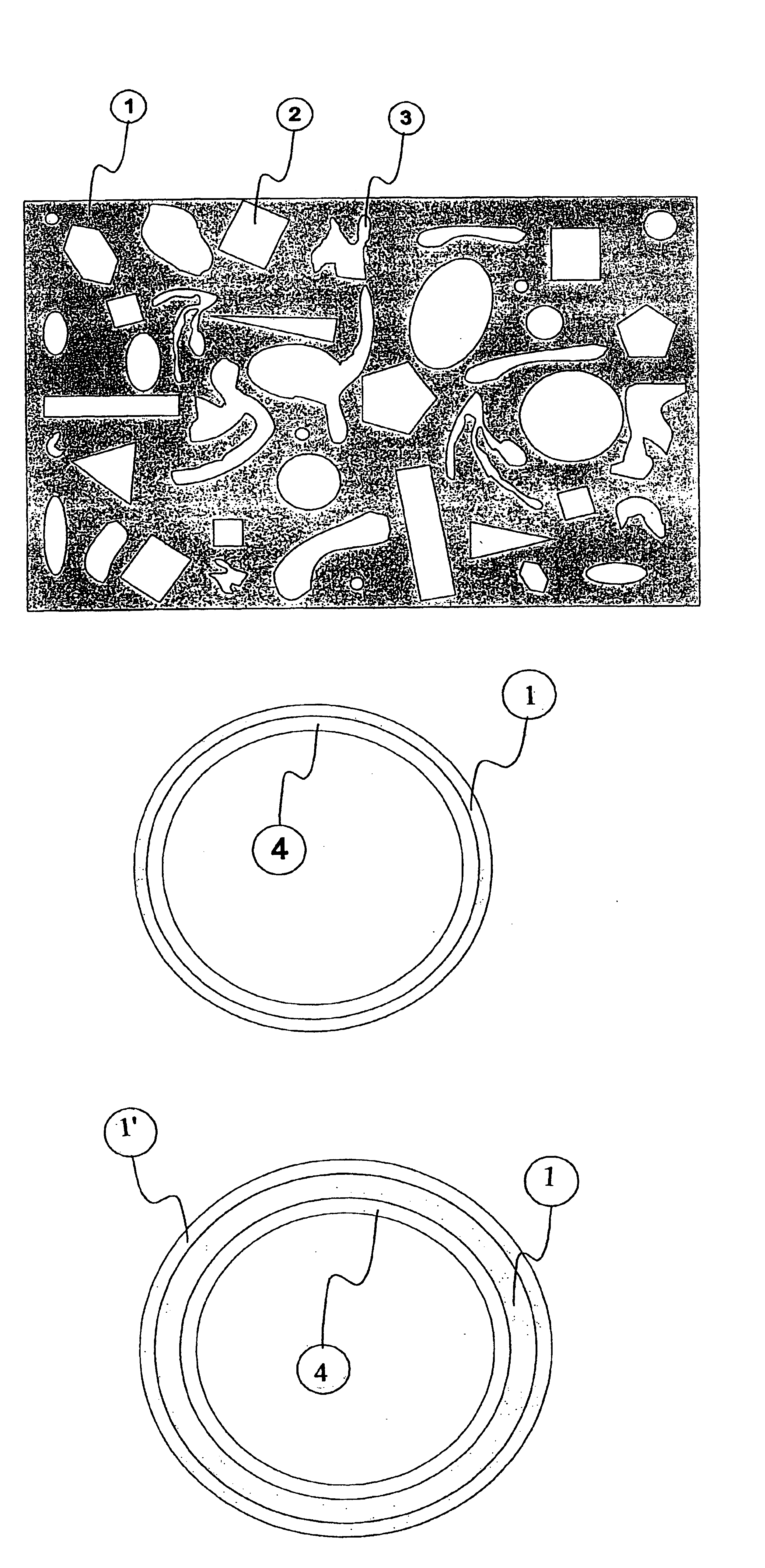
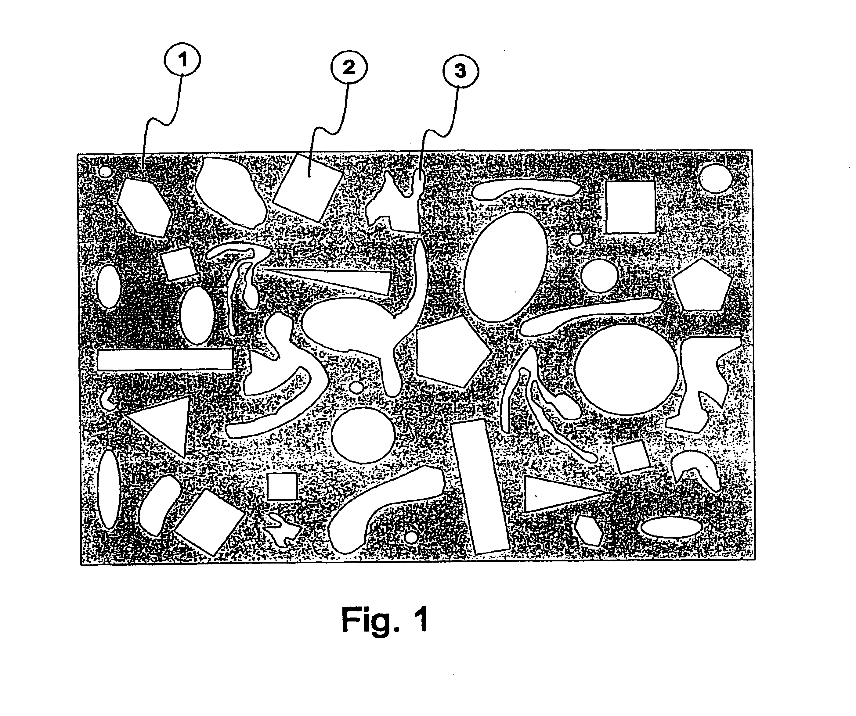
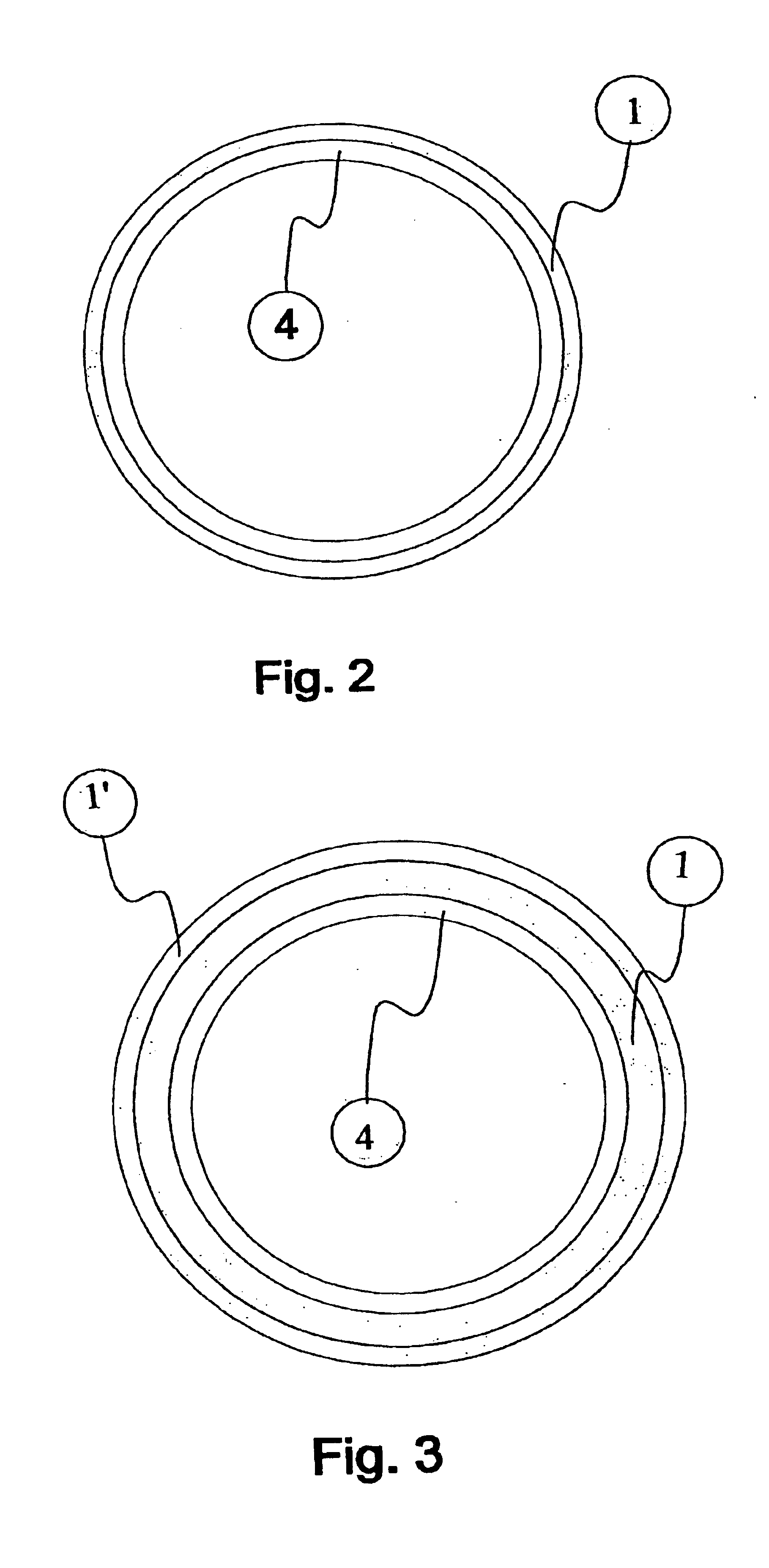
[0009]This object is achieved in accordance with the invention in a surprisingly simple and effective manner in that the field shaping elements are formed from foils and / or sheet metals having openings with a shape, position and size selected such that the shape and amount of the remaining ferromagnetic material produces a desired spatial dependence of the magnetic field in the working volume of the main field magnet with appropriate positioning of the foils and / or sheet metals relative to the working volume of that main field magnet.
[0010]The openings in the foils and / or sheet metals required for the magnetic field correction can be of geometrically simple shapes, e.g. squares, circles, triangles, ellipses etc. or can even assume very bizarre and complex shapes. They can also be a combination of both shape types. These field shaping elements permit optimum utilization of space and therefore transfer of the effectivity of the ferromagnetic field shaping elements (shims). One is neither restricted to certain positions in rails with chambers nor to the size and shape of the shims. Consequently, the software can be driven with fine resolution for determining the cut-outs in the metal sheets and foils. This permits more precise field corrections. In contrast to the conventional passive and manual shim method, the desired field correction can always be carried out without occupation error. This clearly illustrates the reliability of this inventive passive field correction method.

Problems solved by technology

However, in practice there are deviations from the ideal theoretical geometric arrangement of the components of the main field magnet due to mechanical tolerances during production of the main field magnet which can produce actual deviations from the desired constant magnetic field on the order of 1000 ppm.
An unavoidable feature of these systems with a plurality of predetermined locations for the shims is that each of the predetermined locations must have devices for holding the ferromagnetic field shaping elements at the respective location, despite the presence of large magnetic forces.
For this reason, all known means for adjusting the spatial dependence of magnetic fields using ferromagnetic field shaping elements have the disadvantage that a relatively large amount of volume is lost due to the retaining devices themselves and there are gaps between the field shaping elements which cannot be utilized.
In such cases, conventional means for adjusting the spatial dependence of magnetic fields using ferromagnetic field shaping elements cannot be used since the space required is excessively large.
A further disadvantage of these conventional means is that loading must be carried out manually and counting of the required field shaping elements is required for each of the numerous predetermined locations.
Occupation errors are likely, the correction of which is time consuming.

Method used


Image

  • Integral passive shim system for a magnetic resonance apparatus
  • Integral passive shim system for a magnetic resonance apparatus
  • Integral passive shim system for a magnetic resonance apparatus

Examples


Embodiment Construction

[0041]FIG. 6 schematically shows a superconducting main magnet 19 of a nuclear magnetic resonance apparatus with axial room temperature bore 20 according to prior art. The inner wall of the room temperature bore 20 has a plurality of axial guidances 18 into which rails 15 can be inserted. Ferromagnetic field shaping elements 16 in the form of plates of different strengths can be stacked on these rails 15 at various, precisely defined positions 17. The rails 15 are inserted into the guidances 18 and are fastened. These guiding rails can also be part of a support tube, of two substantially flat shim plate supports of a pole shoe magnet, or of a support plate for a one-sided main magnet 19.

[0042]FIG. 7 schematically shows the planar projection of a standard passive shim apparatus for conventional nuclear magnetic resonance magnets. The shim rails 24 are located in the horizontal guidances 23. The shim rails 24 have defined possible positions, also called chambers (e.g. A1, D4, F6 etc.)...


PUM


Abstract

In an arrangement for adjusting the spatial dependence of a magnetic field in a working volume of a main field magnet (19) by means of ferromagnetic field shaping elements (16), the field shaping elements (16) are formed from foils (1, 5, 7, 8) and / or sheet metals (10) having openings (2, 3) whose shape, position and size are selected such that the shape and the amount of the remaining ferromagnetic material produces a desired spatial dependence of the magnetic field in the working volume of the main field magnet for appropriate positioning of the foils (1, 5, 7, 8) and / or sheet metals (10) relative to the working volume of the main field magnet.

Description

[0001]This application claims Paris Convention priority of DE 101 16 505.6 filed on Apr. 3, 2001 the complete disclosure of which is hereby incorporated by reference.BACKGROUND OF THE INVENTION[0002]The invention concerns an arrangement for adjusting the spatial dependence of a magnetic field in a working volume of a main field magnet using ferromagnetic field shaping elements.[0003]An arrangement of this type is known from U.S. Pat. No. 4,990,877.[0004]For magnetic resonance apparatus, an approximately spherical working volume is usually desired and realized in which the magnetic field should be as homogeneous as possible, i.e. the desired spatial dependence of the magnetic field should be a constant. For modern magnetic resonance apparatus which are used in medical diagnosis, the maximum admissible relative deviation of the magnetic field from its average value is typically less than 5 ppm (parts per million) in a working volume with a diameter of approximately half the diameter o...

Claims


Application Information

Patent Timeline
IPC IPC(8): G01R33/3873G01R33/38H01F7/02
CPCH01F7/0278G01R33/3873
Inventor NEUBERTH, GERALD
Owner BRUKER BIOSPIN
Learn More