Radio-wave arrival-direction estimating apparatus and directional variable transceiver

a technology of arrival direction and estimating apparatus, which is applied in the direction of multi-channel direction-finding systems using radio waves, instruments, computing, etc., can solve the problems of accuracy decline and accurate detection of peak directions, and achieve the reduction of the calculation amount of arrival-angle evaluation function, the effect of improving transmitting and receiving quality

Inactive Publication Date: 2005-05-24
PANASONIC CORP
View PDF17 Cites 47 Cited by
  • Summary
  • Abstract
  • Description
  • Claims
  • Application Information

AI Technical Summary

Benefits of technology

[0011]It is an object of the present invention to provide a radio-wave arrival-direction estimating apparatus allowing reduction of a total calculation amount for an arrival-angle evaluation function without causing accuracy degradation of the arrival direction. It is another object of the present invention to provide a directivity variable transceiver for improving transmitting and receiving quality by controlling antenna directivity.
[0012]In the present invention, product of a noise spatial eigenmatrix and a conjugated and transposed matrix of it is a product of an upper or lower triangular matrix. Therefore, the calculation amount for the arrival-angle evaluation function can be reduced in the entire angle range for the estimation of the arrival direction. The arrival angle evaluation using the arrival-angle evaluation function that has a heavy calculation load can be significantly reduced during angle sweeping in the MUSIC method. Processing of the arrival-direction estimating apparatus can be speeded or an apparatus structure can be simplified.

Problems solved by technology

When Δθ increases, a calculation amount in the entire variation range of θ decreases, but the peak direction of the arrival-angle evaluation function cannot accurately detect the peak direction and the accuracy decreases.

Method used


Image

  • Radio-wave arrival-direction estimating apparatus and directional variable transceiver
  • Radio-wave arrival-direction estimating apparatus and directional variable transceiver
  • Radio-wave arrival-direction estimating apparatus and directional variable transceiver

Examples


first exemplary embodiment

1. First Exemplary Embodiment

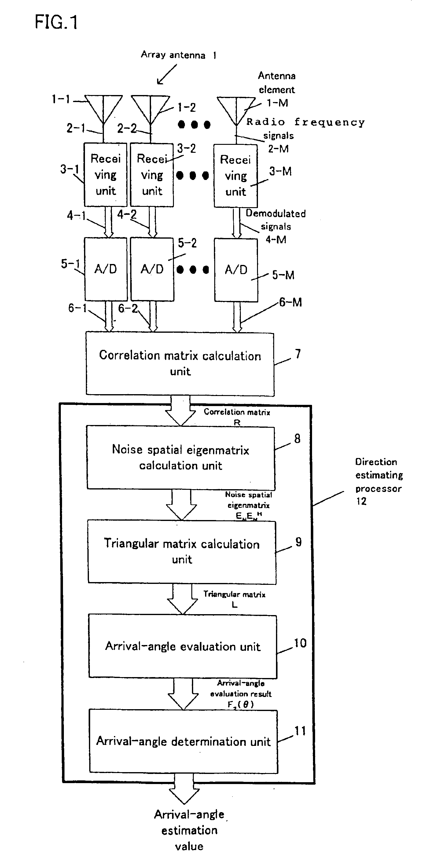
[0032]FIG. 1 is a block diagram of a radio-wave arrival-direction estimating apparatus in accordance with exemplary embodiment 1 of the present invention. Array antenna 1 comprises M(>1) antenna elements 1-1 to 1-M. Antenna elements 1-1 to 1-M receive radio frequency (RF) signals 2-1 to 2-M. Receiving units 3-1 to 3-M connected to antenna elements 1-1 to 1-M convert frequency of the signals and demodulate the converted signals to signals 4-1 to 4-M comprising orthogonal I signal and Q signal. A / D converters 5-1 to 5-M sample respective I signals and Q signals of the demodulated signals 4-1 to 4-M, and convert the demodulated signals to complex digital signals 6-1 to 6-M. Each of the complex digital signals has the I signal in its real part and the Q signal in its imaginary part.

[0033]Correlation matrix calculation unit 7 creates receiving vector x(k) given by Eq.1, using complex digital signals x1(k), x2(k), . . . , xM(k) at sampling time kΔT derived fro...

second exemplary embodiment

2. Second Exemplary Embodiment

[0054]FIG. 4 is a block diagram illustrating the other configuration of direction estimating processor 12 of the radio-wave arrival-direction estimating apparatus of the present invention. Components other than the direction estimating processor in the radio-wave arrival-direction estimating apparatus are similar to those in embodiment 1 described in FIG. 1, so that diagrams and descriptions of these components are omitted. Components different from embodiment 1 will be mainly described hereinafter.

[0055]Operations until correlation matrix R is fed into direction estimating processor 12a are similar to those in embodiment 1. Inverse matrix calculation unit 20 calculates inverse matrix R−1 of correlation matrix R. Because inverse matrix R−1 is a positive definite matrix, triangular matrix calculation unit 21 derives lower triangular matrix L written as

 R−1=LLH  (Equation 13),

using the cholesky factorization.

[0056]Using lower triangular matrix L, arrival-...

third exemplary embodiment

3. Third Exemplary Embodiment

[0065]FIG. 5 is a block diagram illustrating the other configuration of direction estimating processor 12 of the radio-wave arrival-direction estimating apparatus of the present invention. Components other than the direction estimating processor in the radio-wave arrival-direction estimating apparatus are similar to those in embodiment 1 described in FIG. 1, so that diagrams and descriptions of these components are omitted. Components different from embodiment 1 will be mainly described hereinafter.

[0066]Operations until correlation matrix R are fed into direction estimating processor 12b are similar to those in embodiment 1.

[0067]Since correlation matrix R is a positive definite matrix, triangular matrix calculation unit 24 derives lower triangular matrix L given by

R=LLH  (Equation 16),

using the cholesky factorization.

[0068]Inverse matrix calculation unit 25 calculates inverse matrix L−1 of lower triangular matrix L.

[0069]Using lower triangular matrix L...


PUM


Abstract

A radio-wave arrival-direction apparatus calculates a correlation matrix of received signals by correlation calculation between antenna elements, and calculates a noise spatial eigenmatrix, of which each row or column is an eigenvector belonging to a noise eigen-space, by eigenvalue factorization of the correlation matrix. The apparatus also factorizes a matrix including a product of the noise spatial eigenmatrix and a conjugated and transposed matrix of it to an upper or lower triangular matrix, using cholesky factorization. The apparatus calculates an angle evaluation value in a predetermined angle range of an arrival-angle evaluation function using the derived upper or lower triangular matrix, and determines an arrival angle based on the calculation result. A calculation amount in a variable angle range can be thus reduced without causing accuracy degradation of arrival direction, in an algorism requiring all angle sweep for arrival angle estimation of MUSIC method or the like.

Description

[0001]This application a continuation of patent application Ser. No. 10 / 635,411, filed Aug. 6, 2003, now U.S. Pat. No. 6,836,245 which is a divisional of application Ser. No. 10 / 020,477, filed Dec. 12, 2001, now U.S. Pat. No. 6,642,888, issued Nov. 4, 2003.FIELD OF THE INVENTION[0002]The present invention relates to a radio-wave arrival-direction estimating apparatus employing an array antenna, and a directivity variable transceiver for varying antenna directivity based on an estimation result from the estimating apparatus.BACKGROUND OF THE INVENTION[0003]An arrival direction of radio wave is conventionally estimated accurately in a method such as Multiple Signal Classification (MUSIC) method, using an array antenna comprising a plurality of antenna elements. The MUSIC method is disposed in R. O. Schmidt, “Multiple Emitter Location and Signal Parameter Estimation”, Institute of Electrical and Electronics Engineers (IEEE) Trans., AP-34, pp. 276-280 (1986). This method includes an alg...

Claims


Application Information

Patent Timeline
Patent Type & Authority Patents(United States)
IPC IPC(8): G01S3/02G01S3/74G06K9/00
CPCG06K9/0057G01S3/74G06F2218/22
Inventor KISHIGAMI, TAKAAKIFUKAGAWA, TAKASHIYUDA, YASUAKIHOSHINO, MASAYUKI
Owner PANASONIC CORP
Why Eureka
Try Eureka