Network processor/software control architecture

Inactive Publication Date: 2005-05-24
IBM CORP
View PDF8 Cites 5 Cited by
  • Summary
  • Abstract
  • Description
  • Claims
  • Application Information

AI Technical Summary

Benefits of technology

[0004]According to the present invention, the overall architecture for a network processor software system is provided which comprises two portions, Control Point (CP) which is a general purpose processor and the NP (network processor) which is a special purpose processor. The architecture of the present invention is based principally upon embedded processors, hardware assist units, and various memory locations in the network processors. Logically, there are three processors which make up the architecture for each network processor. Each of the processors is a pico code processor. The three processors are the guided cell handler (GCH), the general data handler (GDH), and the guided tree handler or guided table handler (GTH). Each of these processors has the ability to execute in parallel, provided the

Problems solved by technology

In many software system architectures, the most critical and time consuming functions are the control functions.
One of the concerns, therefore, is real time events getting stuck in a queue behind other types of control events in the processor which are not time critical, and these time critical events are then not processed quickly.
Delays in processing events which require real time processing directly affect system performance.
If an extensive amount of learning is occurring, this too can quickly tie up the processor and delay real time events from being processed quickly.
Finally, data services, basically the frame movement, when an application requires large amounts of data to be sent or retrieved from memory, can monopolize processor time, delaying real time as well as learning events, such as tree or table building.

Method used


Image

  • Network processor/software control architecture
  • Network processor/software control architecture
  • Network processor/software control architecture

Examples


case ii

Request Frame Destined for the Up GCH

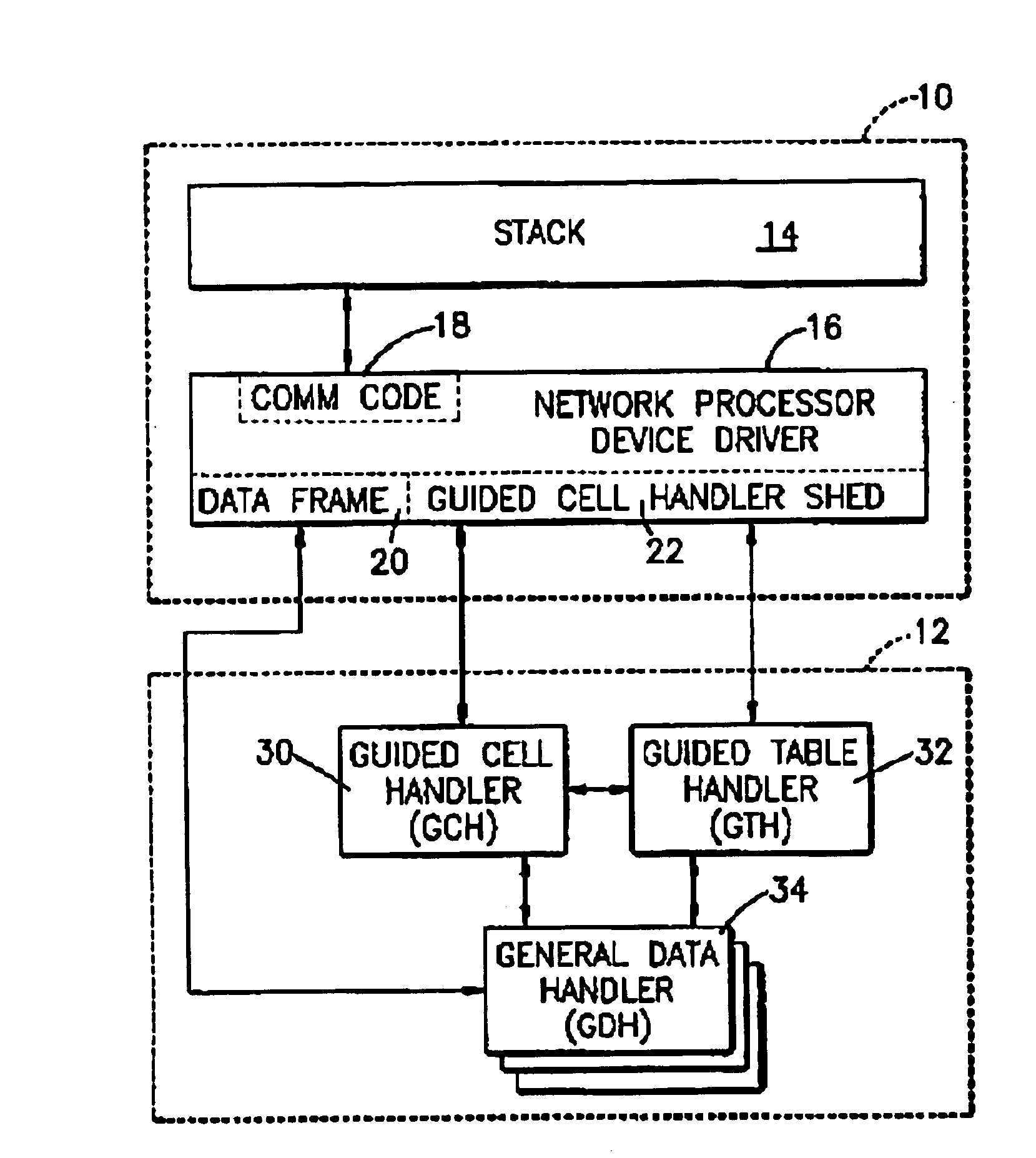
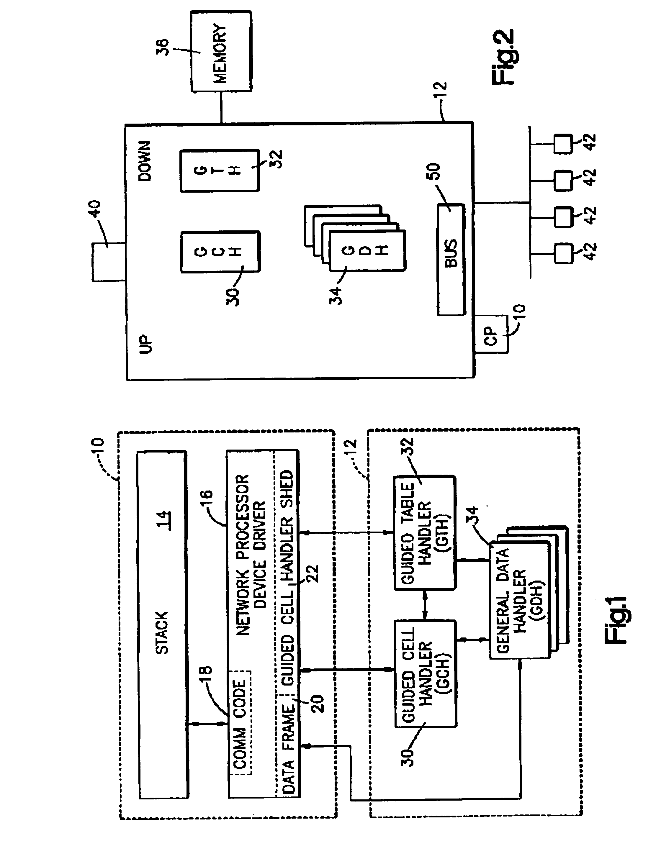
[0066]The message sequence is as follows: 1. A guided frame is generated by the CP 10 and transmitted to the primary network processor 12a, assuming that the frame contains bits that indicate that the frame is targeted for the up GCH residing on a secondary network processor 12b, and that a response is required. 2. The frame is received by the up GCH 30 on the primary network processor 12a and parsed. The results of parsing indicate that the frame is destined for the GCH 30 on a secondary network processor 12b. 3. The frame is dispatched to the target network processor 12b address set appropriately. This causes the frame to be sent to the down GCH 30 residing on the targeted network processor 12b. the down GCH 30 parses the frame and notes that the frame is destined for the upside component of itself. Therefore, it encases the frame to the wrap queue (not shown). This causes the up GCH 30 to receive the frame. 5. The up GCH 30 processes the reque...


PUM


Abstract

The transport protocol for communicating between general purpose processors acting as contact points and network processors in a packet processing environment such as Ethernet is provided. In such an environment, there is at least one single control point processor (CP) and a plurality of network processors (NP), sometimes referred to as blades. A typical system could contain two to sixteen network processors, and each network processor connects to a plurality of devices which communicate with each other over a network transport, such as Ethernet. The CP typically controls the functionality and the functioning of the network processors to function in a way that connects one end user with another, whether or not the end user is on the same network processor or a different network processor. There are three types of communication provided; first, there is communication generally referred to as control services and normally there will be only one pico processor which operates as a GCH (guided cell handler) and only one that operates as a guided tree handler (GTH). A path is provided for the controls to the GCH and the GTH commands, and a separate path is provided for the data frames between the GDH's (general data handler) and the CP.

Description

FIELD OF THE INVENTION[0001]The present invention relates generally to architecture for distributing software functions between a control point or a central processing unit and a plurality of network processors and, more particularly, relates to the architecture within the network processors which allows for distributed processing to take place by having various functions performed by dedicated pico processors on the network processors.BACKGROUND OF THE INVENTION[0002]In many software system architectures, the most critical and time consuming functions are the control functions. There are various different types of control functions, some of which need to occur at once and others that can wait for a period of time. Also, it is necessary that the control functions be performed before the data frames can be exchanged. One of the concerns, therefore, is real time events getting stuck in a queue behind other types of control events in the processor which are not time critical, and these...

Claims


Application Information

Patent Timeline
IPC IPC(8): G06F11/00H04L1/16H04B7/204H04L12/26H04B7/216
CPCG06F15/17
Inventor BASS, BRIAN MITCHELLCALVIGNAC, JEAN LOUISGALLO, ANTHONY MATTEOHEDDES, MARCO C.RINALDI, MARK ANTHONYSIEGEL, MICHAEL STEVENVERRILLI, COLIN BEATONVERPLANKEN, FABRICE JEAN
Owner IBM CORP
Why Eureka
Try Eureka