Optical ring protection apparatus and methods

a technology of optical rings and protection apparatus, applied in the field of optical communication, can solve problems such as inability to pro

Inactive Publication Date: 2005-05-24
TELLABS OPERATIONS
View PDF19 Cites 25 Cited by
  • Summary
  • Abstract
  • Description
  • Claims
  • Application Information

AI Technical Summary

Benefits of technology

[0009]It is another aspect of the invention to protect against light path failure from a source optical node to a sink optical node via at least one intermediate optical node on a per wavelength basis. At the source optical node an output means outputs first and second multiple wavelength signals on respective first and second light paths. The intermediate node is situated in at least one of the first and second light paths and includes an add/drop multiplexer for adding/dropping at least one wavelength to/from the first and second multiple wavelength signals. At the sink optical node a first demultiplexer demultiplexes the first multiple wavelength signal into separate wavelengths, and a second demultiplexer demultiplexes the second multiple wavelength signal into separate wavelengths. For each demultiplexed separate wavelength signal the sink optical node further includes first and second

Problems solved by technology

A problem with WDM system protecting against light path failure at the facility level is that such protection protects only against breaks in the optical fiber carr

Method used


Image

  • Optical ring protection apparatus and methods
  • Optical ring protection apparatus and methods
  • Optical ring protection apparatus and methods

Examples


Embodiment Construction

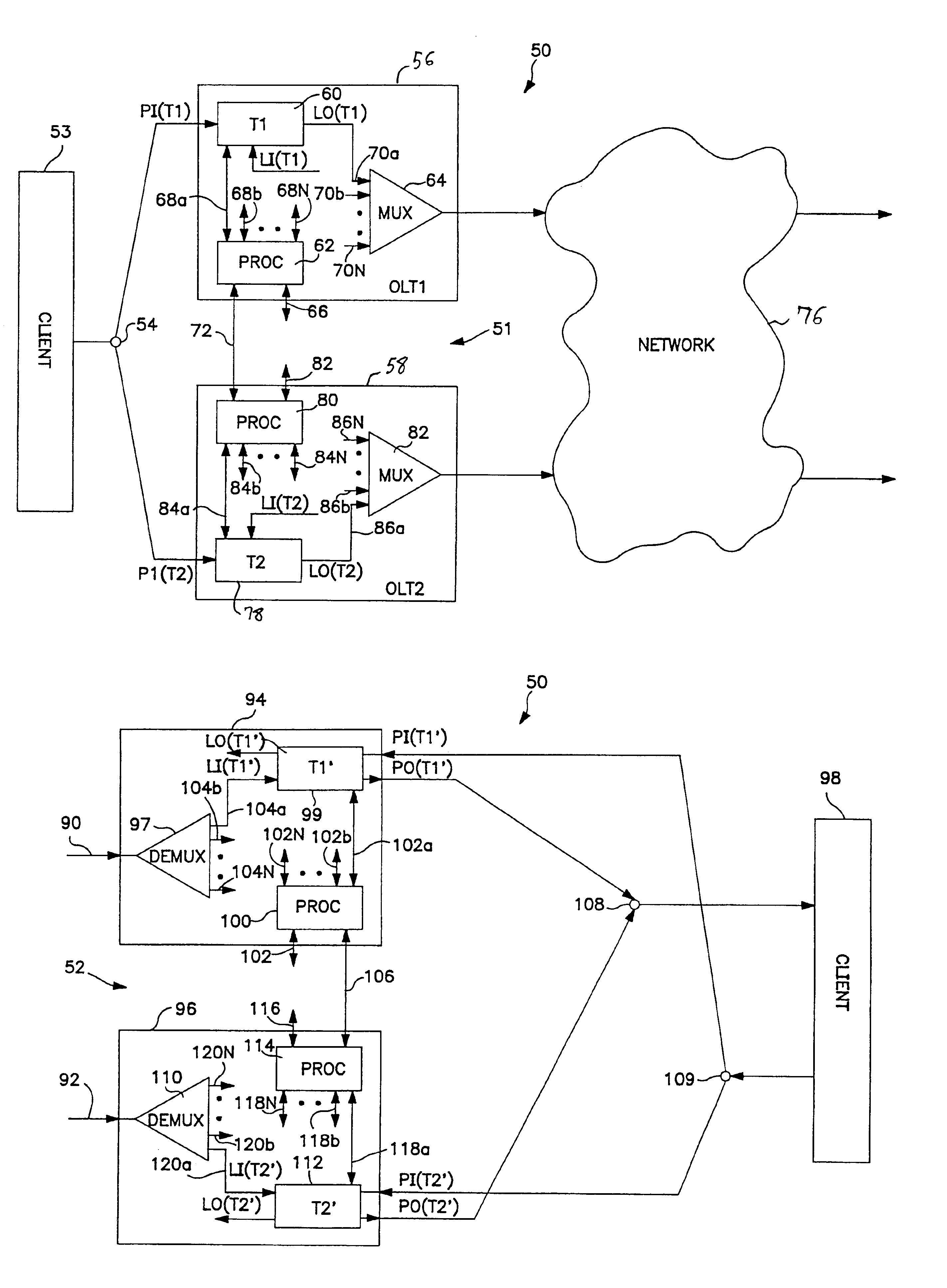
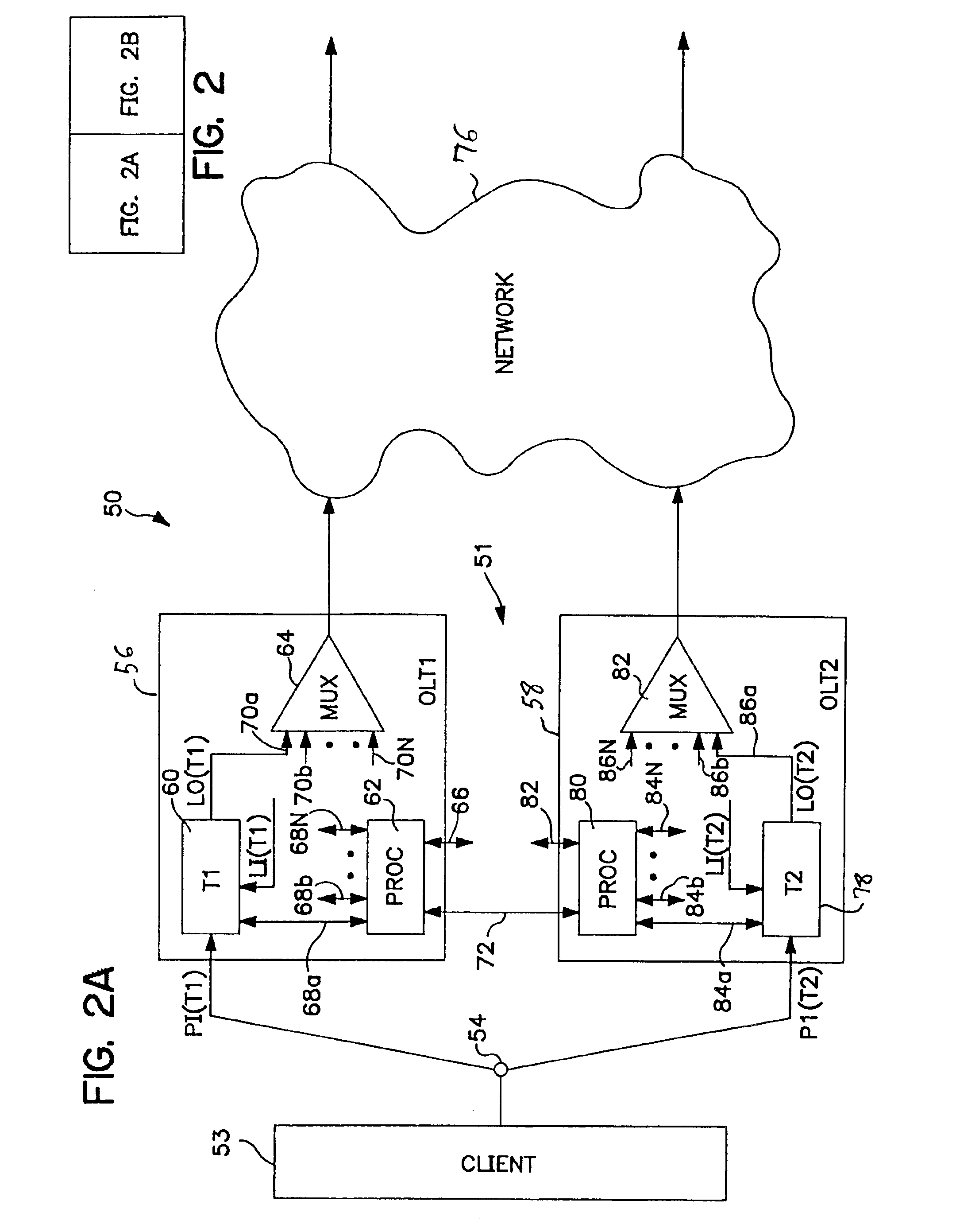
[0013]Refer now to FIG. 2 which is a block diagram of a WDM optical communication system 50 for protecting against light path failure on a per-channel basis when transmitting optical signals from a source optical node 51 to a sink optical node 52 via an optical network 76.

[0014]In the description that follows system operation is described for a single given wavelength in a plurality of wavelengths that are propagated from the source optical node 51 to the sink optical node 52 as a multiple wavelength facility signal, and that at least one intermediate node may be included in the light path which includes an add / drop multiplexer for adding / dropping wavelengths to / from the multiple wavelength facility signal. It is to be appreciated that the remaining ones of the plurality of wavelengths are propagated in a like manner. Likewise, it is understood that the plurality of wavelengths are propagated in the reverse direction from the sink optical node 52 to the source optical node 51 in a s...


PUM


Abstract

An optical communication system comprising plural optical communication paths, a passive optical coupler, and at least one optical node. The passive optical coupler has a plurality of inputs coupled through the passive optical coupler to an output of the passive optical coupler, and each input is coupled in a corresponding one of the optical communication paths. Each optical node comprises plural optical line terminals, each of which is interposed in a corresponding at least one of the optical communication paths. Each optical line terminal is operable to either (a) substantially prevent an optical signal propagating in that corresponding at least one optical communication path from reaching a corresponding input of the passive optical coupler through the at least one optical communication path, or (b) permit the optical signal to propagate in that corresponding at least one optical communication path towards the corresponding input of the passive optical coupler.

Description

CROSS-REFERENCE TO RELATED APPLICATIONS[0001]This application claims the benefit of U.S. Provisional Application No. 60 / 112,412, filed Dec. 14, 1998.FIELD OF THE INVENTION[0002]The invention is in the field of optical communications, and more particularly, pertains to a Wavelength Division Multiplexed (WDM) optical communication system in which light path failure is protected against on a per-channel wavelength basis using passive optics such as splitters and couplers.BACKGROUND OF THE INVENTION[0003]In WDM links protection against light-path failure is typically at a facility level utilizing active optics such as optical switches. For example, as shown in FIG. 1, a double light path connection for a multiple wavelength signal, i.e. a light path connection having a working optical fiber 2 and a redundant optical fiber 4 is connected between optical nodes 6 and 8 in an optical telecommunication system.[0004]At the node 8 of the receive side, the two optical fibers 2 and 4 are combine...

Claims


Application Information

Patent Timeline
IPC IPC(8): H04J14/02H04B10/00H04L1/22
CPCH04B10/032H04L1/22H04J14/0293H04J14/0294H04J14/029H04J14/0282
Inventor GERSTEL, ORNAN A.RAMASWAMI, RAJIV R.
Owner TELLABS OPERATIONS
Why Eureka
Try Eureka