Apparatus and methods for monitoring encoder signals

a technology of encoder signals and apparatus, applied in the direction of digital signal error detection/correction, instruments, coding, etc., can solve the problems of loss of encoder calibration, significant loss of product, revenue, time,

Inactive Publication Date: 2005-05-24
JANNOTTA LOUIS J
View PDF6 Cites 15 Cited by
  • Summary
  • Abstract
  • Description
  • Claims
  • Application Information

AI Technical Summary

Benefits of technology

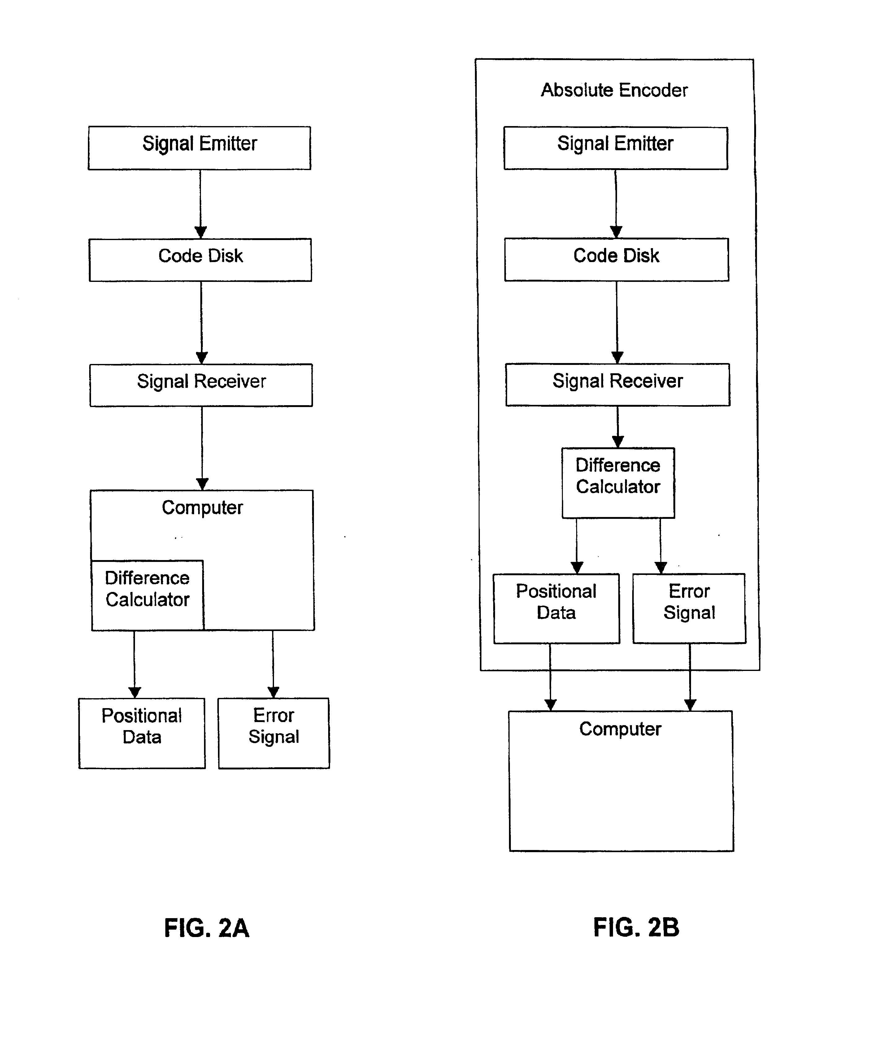
[0026]As disclosed herein, the encoder may be an absolute optical encoder. An absolute optical encoder apparatus may comprise one or more code disks between the signal emitter and signal receiver. The signal emitter may be a light emitting diode, and the signal receiver may be a phototransistor. The code disks of the absolute optical encoder contain a plurality of code words in a gray code format. In one embodiment, the code disks utilize a modified gray code format. In certain embodiments of the invention, the absolute optical encoder comprises two code disks. The encoder of the invention further comprises means for generating an alarm signal when a signal error is detect

Problems solved by technology

Because the information transmitted by incremental encoders is relative to a reference point, an interruption of power to the incremental encoder results in a loss of the calibration of the encoder.
A change of more than one bit at any given point in time could cause an error in interpreting the signal.
In certain industries, such as the petroleum industry, an error in measuring liquid height even over a small time period, may result in a significant loss of product, revenue, and time.
In addition, the code disks

Method used


Image

  • Apparatus and methods for monitoring encoder signals
  • Apparatus and methods for monitoring encoder signals
  • Apparatus and methods for monitoring encoder signals

Examples


Embodiment Construction

[0033]In one particular embodiment of the invention, the methods of the invention are practiced utilizing an encoder system for monitoring liquid height in storage tanks. An example of such an encoder system is disclosed in U.S. Pat. No. 4,342,996 (the '996 patent, by Jannotta). The encoder systems may be used to monitor liquid heights in one or more storage tanks.

[0034]In general, liquid height in a storage tank is conventionally determined using a float-type mechanical gage. The float, which moves up and down in response to changes in liquid height, is attached to a gage shaft which rotates in response to the movement of the float. Thus, by calibrating the rotational position of the gage shaft with various heights of liquid, the liquid height at any given time can be determined by observing the rotational position of the gage shaft.

[0035]As disclosed in the '996 patent, an absolute encoder may be employed to monitor, without recalibration, the liquid height in a tank even in the e...


PUM


Abstract

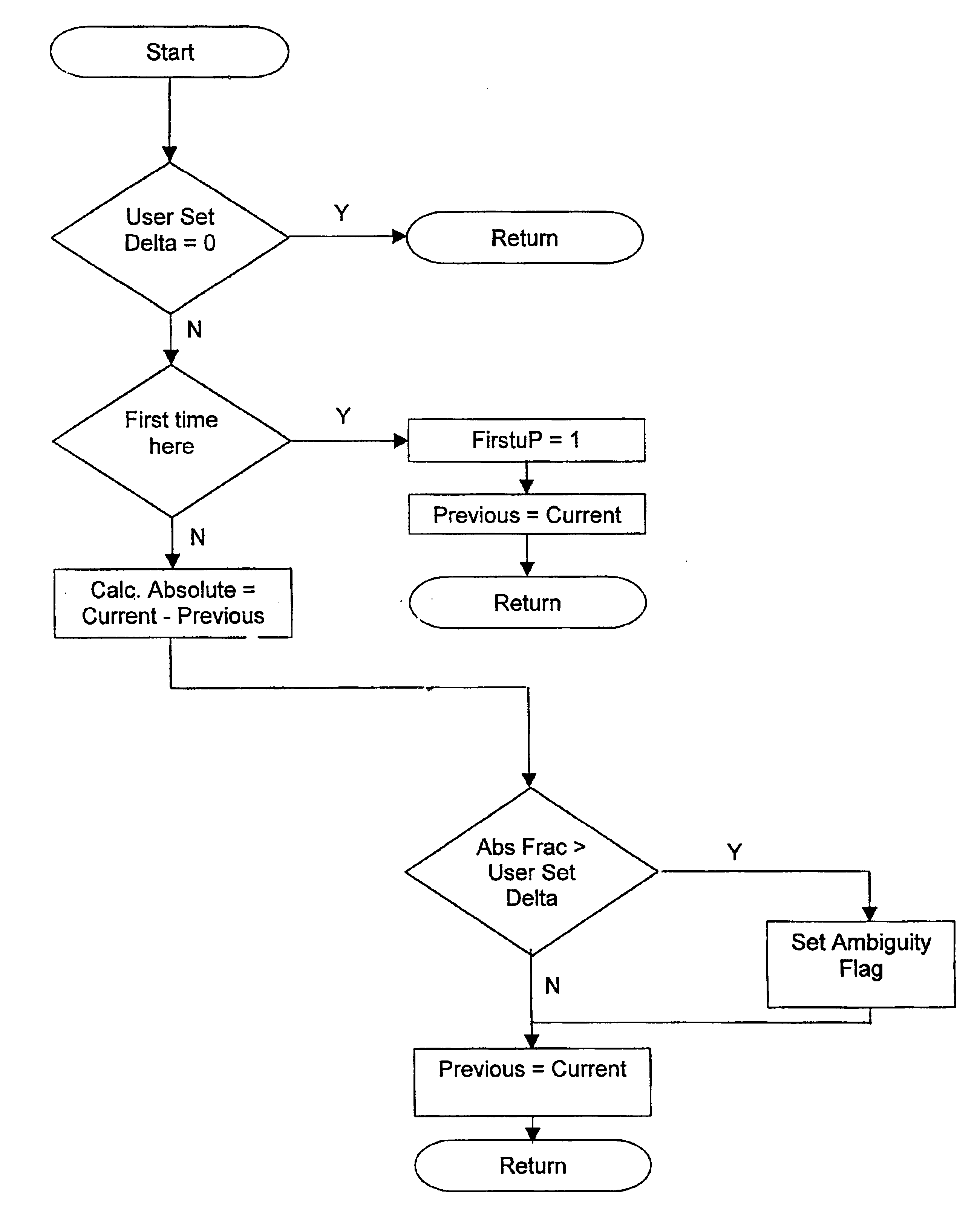
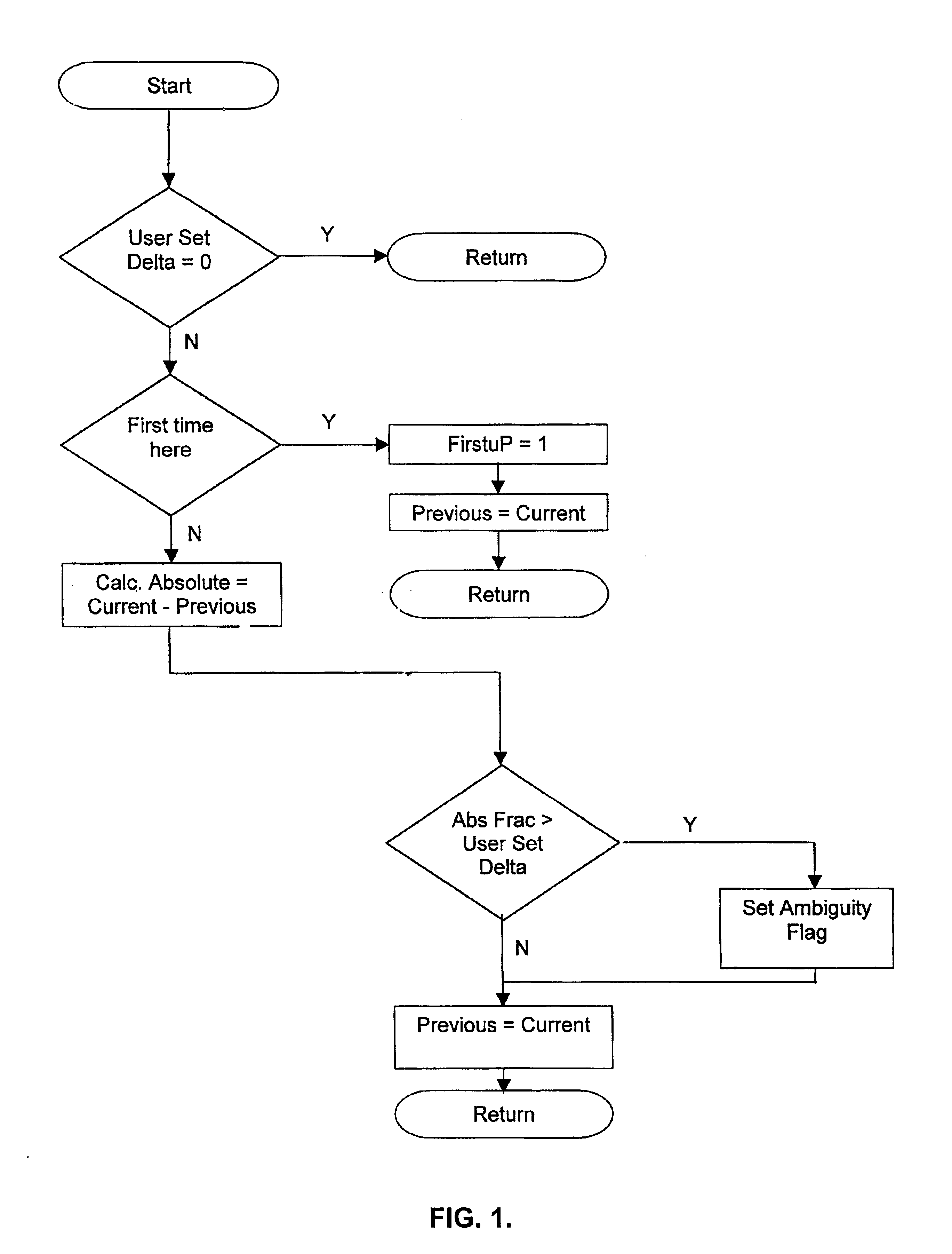
Methods for monitoring the accuracy of positional measurements by encoders that translate positional information into signals include determining the difference between two signals generated by the encoder and comparing the difference to a threshold value. Differences greater than the threshold indicate an error in measurement by the encoders. The methods may be practiced using one or more computer programs. The methods may be practiced with any encoder, including absolute and incremental encoders. Encoders include components to implement the methods.

Description

[0001]The present invention relates to an apparatus and methods for monitoring encoder signals, and in particular, apparatus and methods for monitoring the accuracy of signals generated by encoders, preferably optical encoders.[0002]Various patents, publications and references are cited herein. The contents of all of such patents, publications, and references, in their entireties, are incorporated herein by reference.BACKGROUND OF THE INVENTION[0003]Encoders are typically used to translate positional information into signals that can be processed and analyzed. Encoders are well-known in the art. For example, encoders may be obtained from BEI Technologies (Goleta, Calif., U.S.). Encoders may be optical encoders. Encoders may be incremental optical encoders or absolute optical encoders.[0004]Generally, optical encoders (either incremental or absolute optical encoders) translate angular or linear positional information into electrical output signals. Signal processing electronics may b...

Claims


Application Information

Patent Timeline
IPC IPC(8): G06F11/00G11B7/00H03M13/00G01D5/36H03M1/10H03M1/24H03M7/16
CPCG01D5/36H03M1/1071H03M7/16H03M1/24
Inventor JANNOTTA, LOUIS J.
Owner JANNOTTA LOUIS J
Why Eureka
Try Eureka