Eureka AIR delivers breakthrough ideas for toughest innovation challenges, trusted by R&D personnel around the world.

Sawing apparatus and saw fence system

a technology of sawing apparatus and sawing fence, which is applied in the field of sawing apparatus, can solve the problems of ineffective devices, inability to provide adequate and effective support for workpieces, and difficulty in adjustment, and achieve the effect of convenient and convenient adjustmen

Inactive Publication Date: 2005-05-31
BLACK & DECKER INC
View PDF47 Cites 26 Cited by
  • Summary
  • Abstract
  • Description
  • Claims
  • Application Information

AI Technical Summary

Benefits of technology

[0015]It is a feature of the present invention to provide a workpiece guide for a cutting device having a unique infeed surface that provides consistent support to a workpiece during cutting operations.
[0016]It is another feature of the present invention to provide a workpiece guide for a saw having a unique infeed surface that is easily and readily adjustable relative to the work surface of the saw.
[0018]Yet another feature of the present invention is to provide a workpiece guide for a saw having a work surface that provides a more convenient apparatus for securing the workpiece guide to the work surface of the saw prior to cutting operations and for readjusting the workpiece guide to the work surface of the saw during cutting operations.

Problems solved by technology

Presently available workpiece fences adapted for use with powered table saws typically are not constructed so as to support the workpiece during cutting operations.
In particular, the presently available table saw fences do not provide adequate and effective support to a workpiece when performing lengthwise or “rip” cuts.
However, such devices have proven to be ineffective for a number of reasons.
In particular, they fail to provide consistent support to the workpiece throughout their surfaces, they generally are difficult to adjust relative to the plane of the work surface of the saw, and they may at least partially obstruct the area in front of the saw that is normally occupied by the operator.
Compounding the relative lack of utility of many of the available table saw fences is the fact that presently available table saws, and other sawing or cutting devices including work surfaces, generally do not provide convenient means for securing accessory devices, such as workpiece fences and the like, to the work surface.
In particular, the design of commonly available table saw rails do not provide for rapid readjustment of the workpiece fence during cutting operations.
In addition, the commonly available rails often require a gap between the table saw's work surface and the rail.
In addition, commonly available powered table saws typically lack effective means for providing for the disposal of debris produced by the cutting operations.
In particular, in commonly available powered table saws, debris produced by cutting operations, for example saw dust, stock, and other scrap, falls from the work surface to the floor areas beneath and around the perimeter of the saw, thereby complicating clean up and generally lending an untidy appearance to the workshop.
There is still another need for a saw dust / saw scrap collection system that does not allow such material to collect beneath and around the perimeter of the table saw or other sawing device.

Method used


Image

  • Sawing apparatus and saw fence system
  • Sawing apparatus and saw fence system
  • Sawing apparatus and saw fence system

Examples


Embodiment Construction

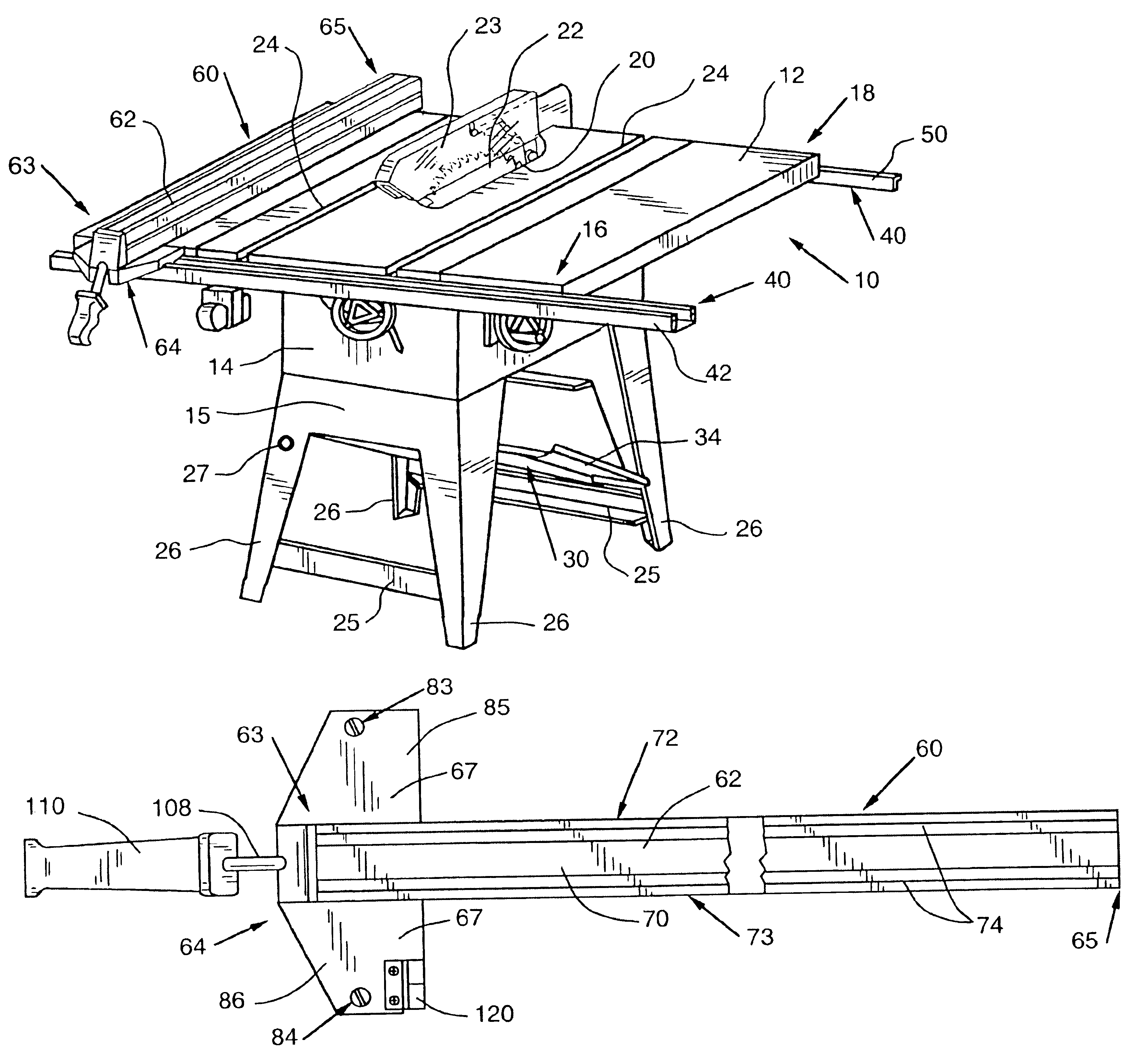
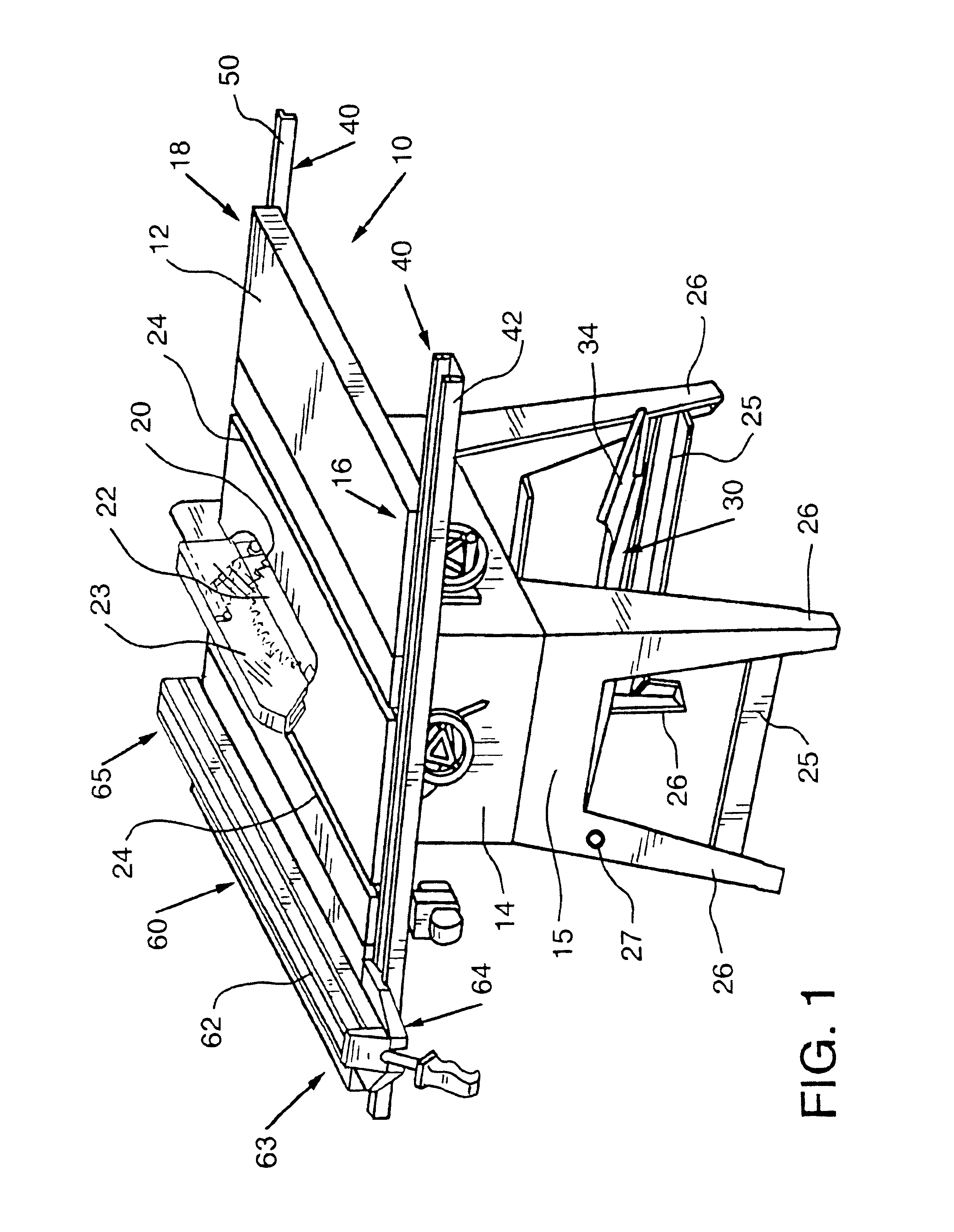
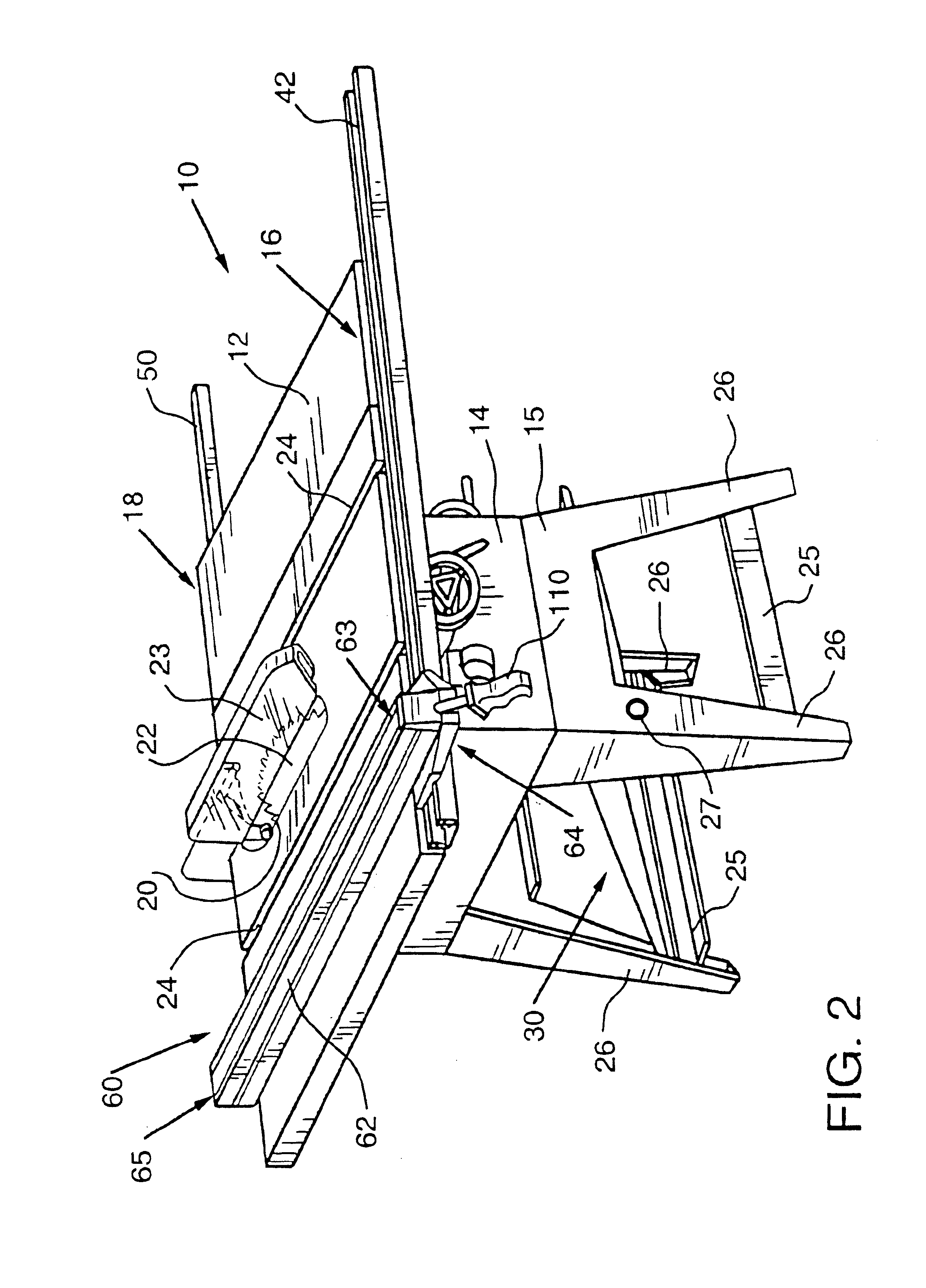
[0043]Referring now to the drawings for the purpose of illustrating embodiments of the inventions only and not for the purposes of limiting the same, the figures show the present inventions adopted for use in connection with a powered table saw 10. While the present inventions are particularly well-suited for use in connection with a powered table saw 10, one of ordinary skill in the art will appreciate that the present inventions may be successfully employed in connection with various other types of saws and cutting devices having workpiece support surfaces, such as miter saws, band saws, and the like. Accordingly, the protection afforded to the inventions claimed herein may not be limited solely to their use in connection with a table saw 10 of the type depicted in the present figures. Because the general mode of operations of powered table saws is well known, only those features of the table saw 10 that are helpful in illustrating the mode of embodiments of the present inventions...


PUM

PropertyMeasurementUnit
elevationaaaaaaaaaa
distanceaaaaaaaaaa
angleaaaaaaaaaa

Abstract

A sawing apparatus and a saw fence. The saw apparatus may include a work surface. The saw may include a rail system disposed along the edges of the work surface, for the attachment of accessories thereto. The saw may be provided with workpiece guide adapted to be attached to the rail system for guiding workpieces during the operation of the saw. The workpiece guide may also be provided with an infeed extension that rides on the rail system and is capable of supporting workpieces during the operation of the saw. The infeed extension may be adjusted relative to the work surface of the saw. The saw may further be provided with a debris collection system for the collection of debris produced by the cutting operations of the saw.

Description

CROSS-REFERENCE TO RELATED APPLICATIONS[0001]Not applicable.STATEMENT REGARDING FEDERALLY SPONSORED RESEARCH AND DEVELOPMENT[0002]Not applicable.TECHNICAL FIELD AND INDUSTRIAL[0003]Applicability of the Invention[0004]The present invention relates to sawing apparatus including a work surface for supporting a workpiece, and more particularly relates to a powered table saw including a rail system for positioning of a fence on the work surface of the saw and that may further include a dust collection system for channeling and collecting dust created during the sawing operation. The present invention also relates to a device for positioning a workpiece on the work surface of a sawing apparatus and more particularly relates to a table saw fence for positioning a workpiece on the work surface of the saw relative to the circular blade of the saw including an adjustable integral support member for at least partially supporting the workpiece when it is being advanced along the work surface of...

Claims


Application Information

Patent Timeline
Patent Type & Authority Patents(United States)
IPC IPC(8): B27B27/02B27B27/00
CPCB27B27/02Y10T83/727Y10T83/741Y10T83/773Y10T83/2216Y10T83/732Y10T83/222Y10T83/7684
Inventor MILLER, DAVID
Owner BLACK & DECKER INC
Why Eureka
Eureka Blog
Learn More