Vapor recovery fuel dispenser for multiple hoses

Inactive Publication Date: 2005-05-31
GILBARCO
View PDF64 Cites 40 Cited by
  • Summary
  • Abstract
  • Description
  • Claims
  • Application Information

AI Technical Summary

Benefits of technology

[0034]An advantage of the invention as disclosed herein and in our earlier patent applications Ser. No. 625,892 filed Dec. 11, 1990 and its continuation Ser. No. 824,702 filed Jan. 21, 1992 (now U.S. Pat. No. 5,156,199), is that the nozzle used to fill the automobile tank need not be equipped with bellows or other face sealing means. Gasoline customers who use vapor recover

Problems solved by technology

Other volatile liquids such as hydrocarbon fluids raise similar issues.
Balance systems have numerous drawbacks, including cumbersomeness, difficulty of use, ineffectiveness when seals are poorly made, and slowed fueling rates.
In particular, since the vapor pump is independently driven, in the event of a malfunction so that the vapor pump is operating when the liquid pump is not, there is a possib

Method used


Image

  • Vapor recovery fuel dispenser for multiple hoses
  • Vapor recovery fuel dispenser for multiple hoses
  • Vapor recovery fuel dispenser for multiple hoses

Examples


Embodiment Construction

Temperature Compensation

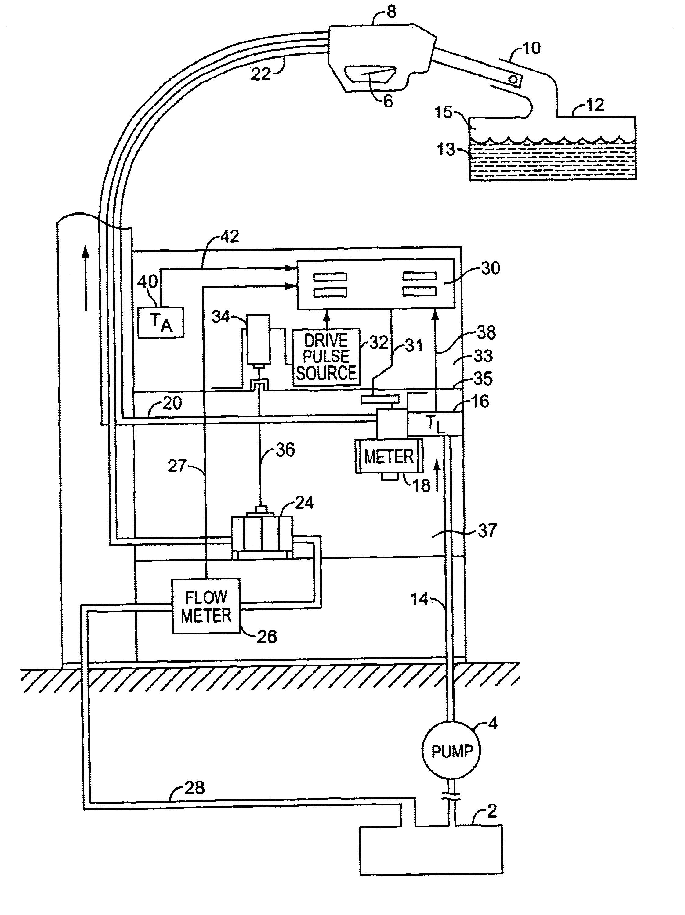
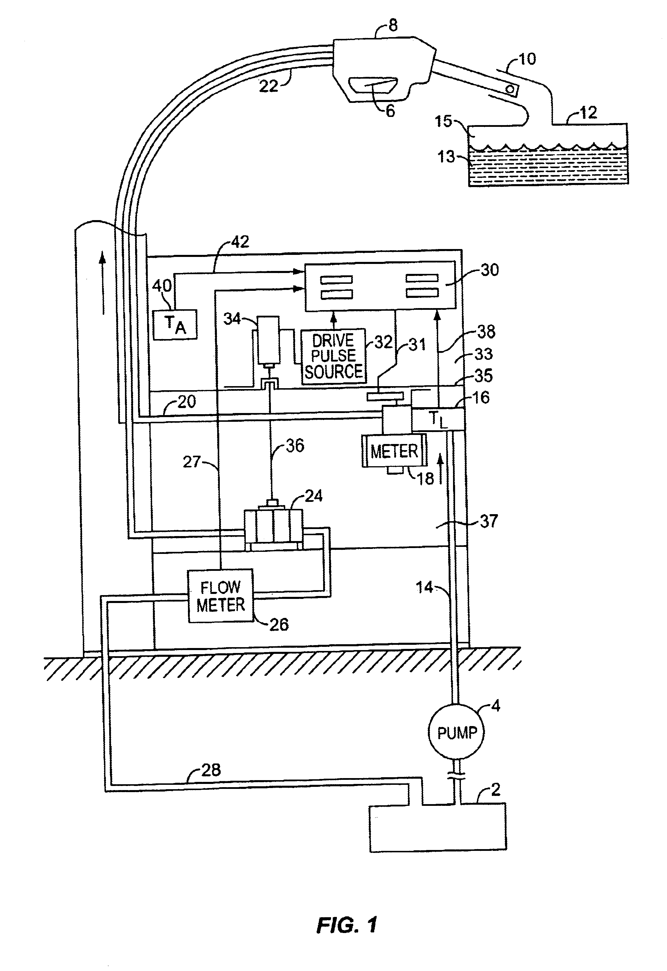
[0042]In the embodiment of the invention shown in FIG. 1, liquid is pumped from a reservoir 2 by a pump 4 with a volumetric flow VL that is determined by the position of a trigger 6 of a nozzle 8. The nozzle 8 is a bellows-free and seal-free nozzle, such as the one described in U.S. Pat. No. 4,199,012, for example, and is inserted into the fill pipe 10 of a tank 12 that is to be filled with liquid 13. The liquid flows to the nozzle from the pump 4 via a tube 14, a temperature transducer 16, a flow meter 18, and a tube 20. As vapor 15 is forced from a tank 12, it is drawn through a tube 22 by a pump 24 that forces it through a flow meter 26 and a tube 28 to the reservoir 2.

[0043]As described below, means are provided for initially driving the recovery pump 24 at such speed that its volumetric flow, VV, equals the volumetric flow, VL, of the liquid produced by the pump 4. Signals from the flow meter 18 are applied via a lead 31 to a microprocessor 30 that is pr...


PUM

PropertyMeasurementUnit
Pressureaaaaaaaaaa
Flow rateaaaaaaaaaa
Volumeaaaaaaaaaa

Abstract

A dispensing system for dispensing volatile liquids such as hydrocarbon fuel for vehicles into a tank having a filler neck also collects the vapors to reduce atmospheric pollution. A fuel delivery hose includes a hand-held fuel valve and nozzle for insertion in the opening of the tank. A means delivers fuel under pressure to the fuel delivery hose, and another means provides electrical pulses corresponding to the volumetric flow of liquid through the fuel delivery hose when the fuel valve is open. A vapor recovery hose includes a vapor intake connected to the hand-held nozzle for insertion in the opening of the tank without sealing with the tank, and a motor driven vapor pump produces a volumetric flow through the vapor recovery hose corresponding to a signal applied to the motor. A processing means produces the signal applied to the motor in response to the electrical pulses to produce a volumetric flow of vapor slightly greater than the volumetric flow of fuel to the tank.

Description

RELATED APPLICATIONS[0001]This application is a continuation-in-part of application Ser. No. 07 / 946,741 filed Sep. 16, 1992, now U.S. Pat. No. 5,955,915 which is a continuation-in-part of application Ser. No. 07 / 824,702 filed Jan. 21, 1992, (now U.S. Pat. No. 5,156,199 issued Oct. 20, 1992) which is a continuation of application Ser. No. 07 / 625,892 filed Dec. 11, 1990, now abandoned. The disclosures of application Ser. No. 07 / 946,741 and U.S. Pat. No. 5,156,199 are hereby incorporated by reference.FIELD OF THE INVENTION[0002]U.S. patent application entitled “Vapor Recovery System for Fuel Dispenser” filed on May 21, 1990, in the name of Kenneth L. Pope, and bearing Ser. No. 07 / 526,303 now U.S. Pat. No. 5,040,577.[0003]The field of the present invention relates generally to fuel dispensers, and more particularly to vapor recovery systems for use when dispensing a volatile fuel such as gasoline.BACKGROUND OF THE INVENTION[0004]Vapor recovery fuel dispensers, particularly gasoline disp...

Claims


Application Information

Patent Timeline
IPC IPC(8): B67D5/01B67D5/04B67D5/32B67D7/04B67D7/32
CPCB67D7/32B67D7/0486
Inventor HARTSELL, JR., HAL C.POPE, KENNETH L.
Owner GILBARCO
Why Eureka
Try Eureka