Glide head for asperity detection

a technology of asperity detection and glide head, which is applied in the direction of mechanical roughness/irregularity measurement, heat measurement, instruments, etc., can solve the problems of reducing the energy of impact, affecting the accuracy of asperity detection,

Inactive Publication Date: 2005-05-31
SEAGATE TECH LLC
View PDF57 Cites 29 Cited by
  • Summary
  • Abstract
  • Description
  • Claims
  • Application Information

AI Technical Summary

Problems solved by technology

The glide quality of a disc is related to the disc smoothness, although other defects also may alter glide quality.
For example, ...

Method used


Image

  • Glide head for asperity detection
  • Glide head for asperity detection
  • Glide head for asperity detection

Examples


Embodiment Construction

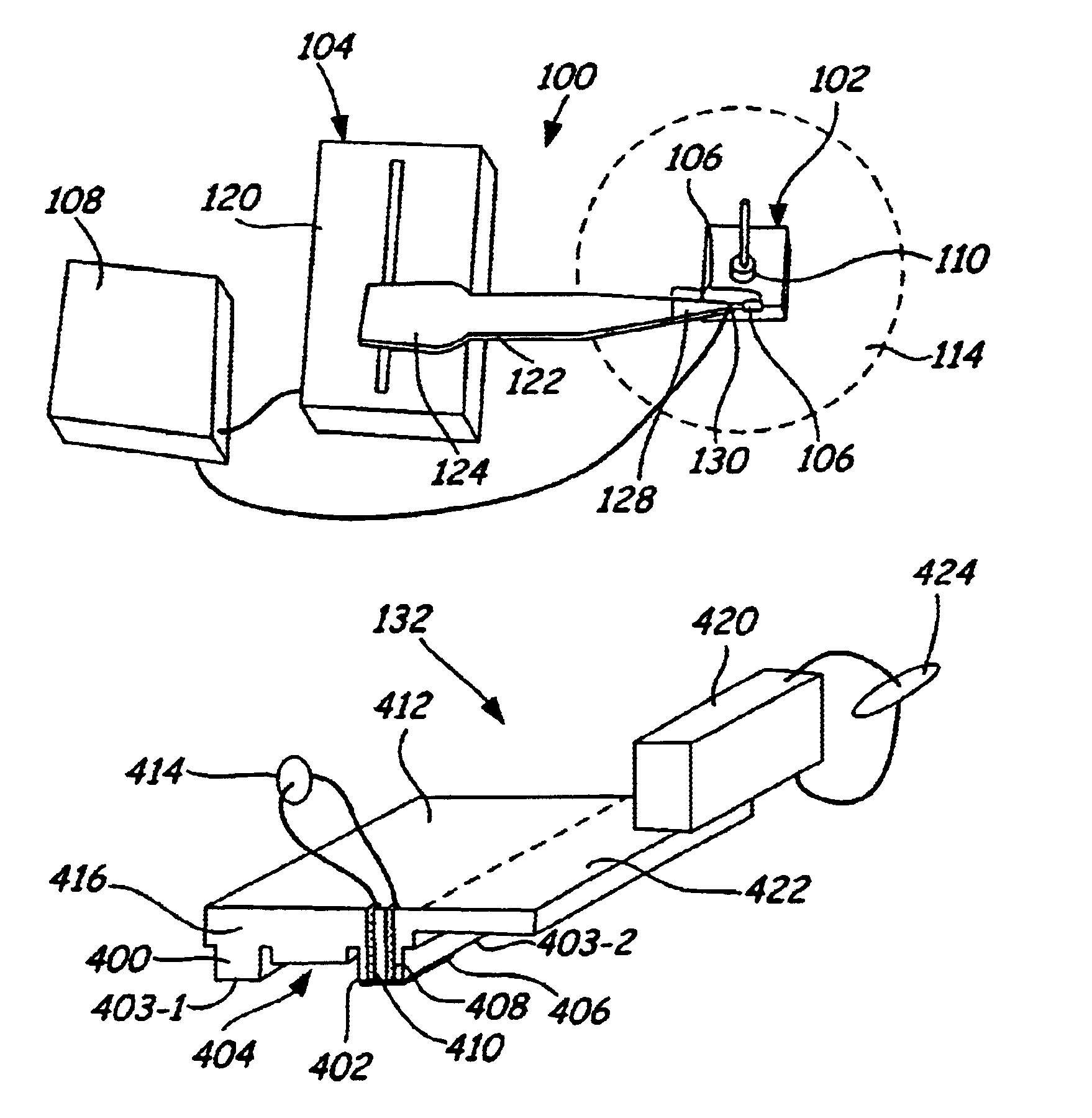
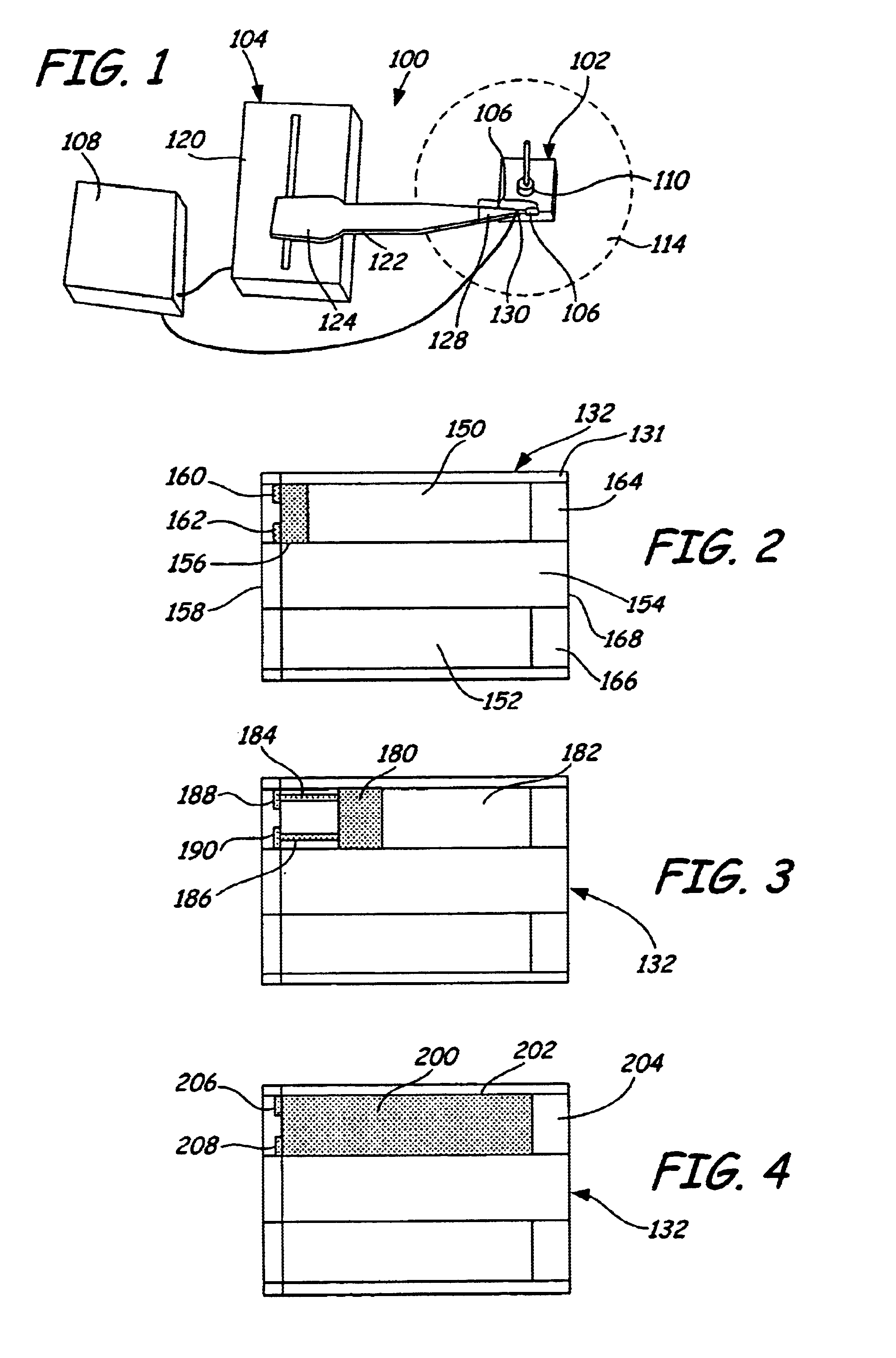
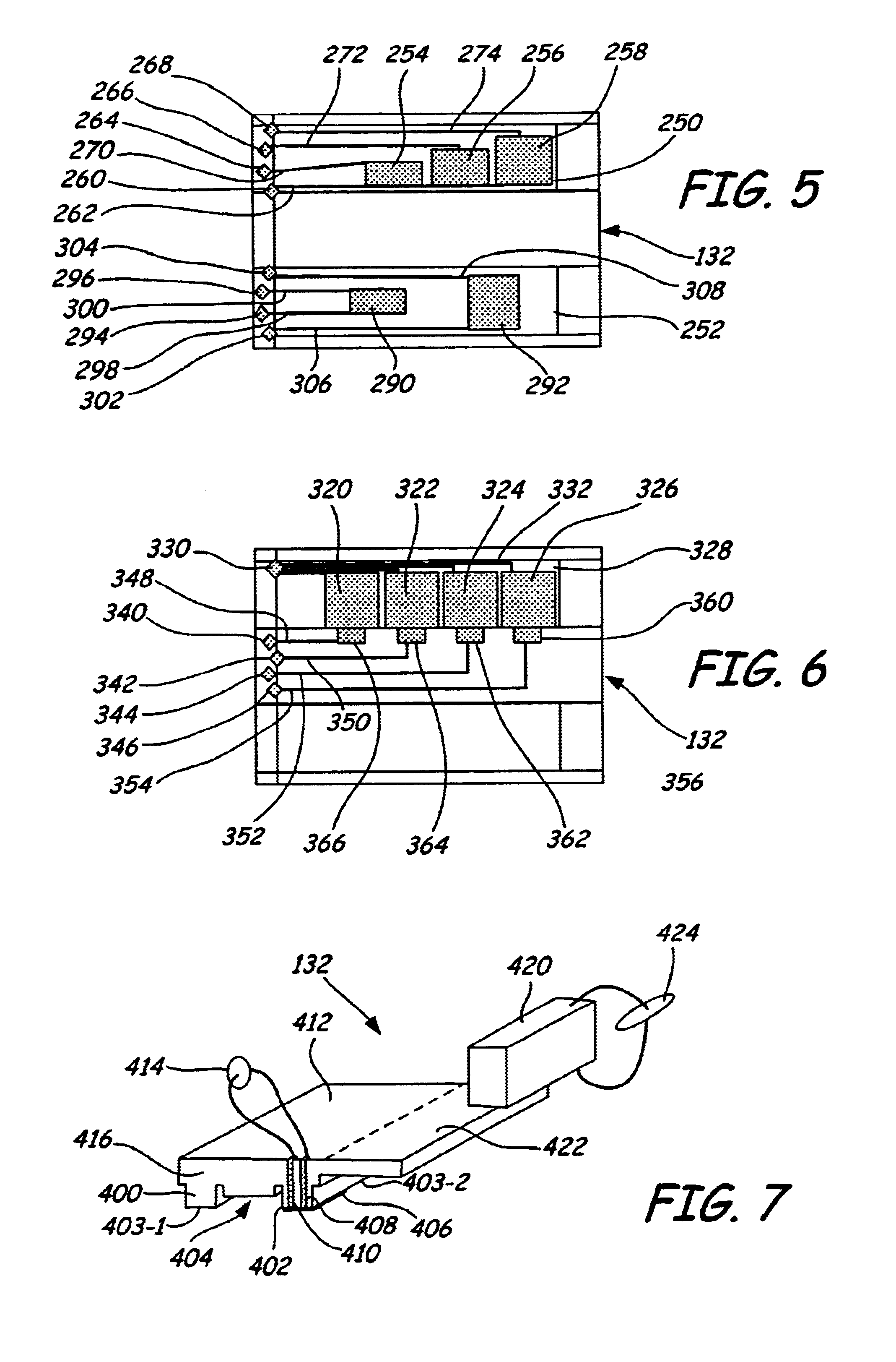
[0019]By placing a thermal transducer as an defect / asperity sensor on the air bearing surface of a slider / glide head, glide testing can be performed efficiently with a high sensitivity. After a defect strikes the thermal transducer, a resistance spike is detected to provide a signature that a defect has contacted the glide head. Furthermore, thermal transducers oriented along the air bearing surface can present a large contact area on the air bearing surface. Thus, a glide test can be performed efficiently since asperities with a greater range of heights strike the thermal transducer when contacting the glide head. A plurality of thermal transducers on the air bearing surface can be used to assess the distribution of defect heights.

[0020]Glide tests performed with piezoelectric (PZT) transducers can be accomplished efficiently since defects with a wide range of heights are detected in one pass over a section of the disc. It is believed, though, that glide heads with PZT transduc...


PUM

PropertyMeasurementUnit
Electrical conductivityaaaaaaaaaa
Electrical conductoraaaaaaaaaa
Distanceaaaaaaaaaa

Abstract

Glide heads for the detection of asperities on a storage disc have a thermal transducer oriented along the air bearing surface. The thermal transducer generally is in electrical contact with a circuit to measure the electrical resistance of the thermal transducer. Preferred methods of depositing the thermal transducer involve the deposition of the thermal transducer on the smooth surface of a wafer prior to the slicing of individual sliders.

Description

CROSS REFERENCE TO RELATED APPLICATIONS[0001]The present application claims priority to provisional patent application Ser. No. 60 / 082,244, entitled “A Novel Glide Head,” filed on Apr. 16, 1998.BACKGROUND OF THE INVENTION[0002]The present invention relates generally to glide heads for evaluating glide quality of a disc surface, and to related methods. More particularly, the present invention relates to a glide head with a thermal transducer for detecting defects on a disc surface.[0003]Disc drives are used for storing information, typically as magnetically encoded data, and more recently as optically encoded data, on a disc surface. The storage and retrieval operations generally involve “flying” a read and / or write head over the surface. As storage densities increase, the fly height of the heads over the disc surfaces generally are decreased. Consequently, defect heights on the discs must decrease proportionally to reduce or eliminate contacts between the head and disc that could da...

Claims


Application Information

Patent Timeline
IPC IPC(8): G01N25/72G11B33/00G11B23/50G11B33/10G11B5/60G11B5/00G11B5/012
CPCG01N25/72G11B23/505G11B5/6076G11B33/10G11B5/012Y10T29/49048G11B2005/001Y10T29/49041
Inventor SUNDARAM, RAMESHYAO, WEI H.
Owner SEAGATE TECH LLC
Why Eureka
Try Eureka